Unbreakable micro-browser

a micro-browser and eyebrow technology, applied in the direction of instruments, mechanical roughness/irregularity measurements, measurement devices, etc., can solve the problem of re-shaping the rod

Inactive Publication Date: 2005-11-03
AGILENT TECH INC
View PDF5 Cites 0 Cited by
  • Summary
  • Abstract
  • Description
  • Claims
  • Application Information

AI Technical Summary

Problems solved by technology

That leaves the problem of re-shaping the rod.

Method used


Image

  • Unbreakable micro-browser
  • Unbreakable micro-browser
  • Unbreakable micro-browser

Examples


Embodiment Construction

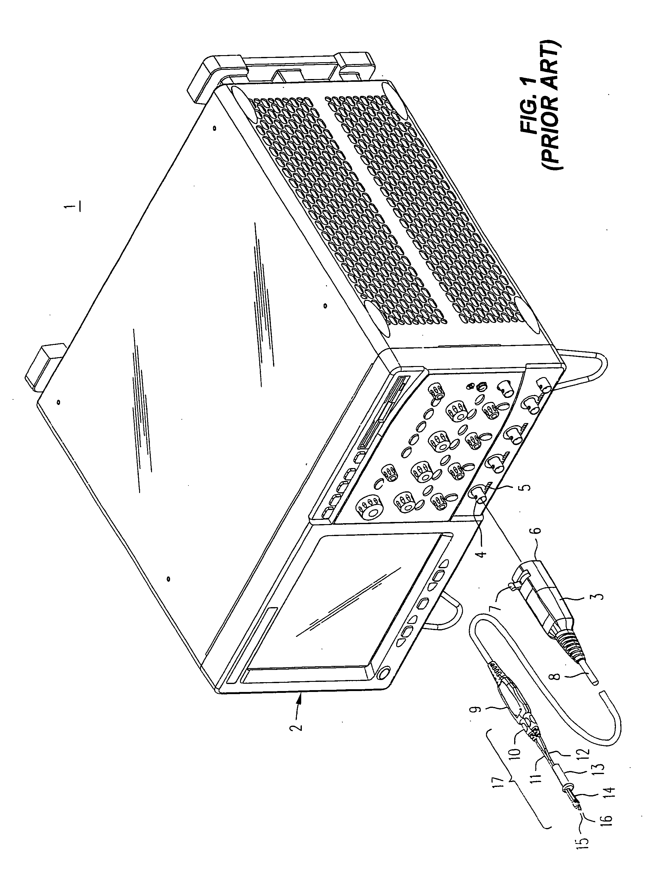
[0015] Refer now to FIG. 1, wherein is shown a front perspective view 1 of an electronic instrument 2, such as a digital oscilloscope, having one or more front panel connectors 4 that receive a push-lock BNC connector 3, say, in support of operation with active probes. In a manner known in the prior art, the push-lock BNC probe housing is installed simply by lining it up and then pushing it toward the 'scope. When the push-lock connector 3 is in place, not only is a BNC connection established to connector 4, but a row of spring loaded pins 6 (not visible) on the front of the housing for the push-lock assembly engages a row 5 of contacts beneath the connector 4. To remove the push-lock connector the operator pushes on lever or tab 7 with a thumb or a finger, while pulling the assembly away from the 'scope. A main cable 8 carries both power to, and signal information from, an amplifier pod 9, which may contain high frequency amplifiers.

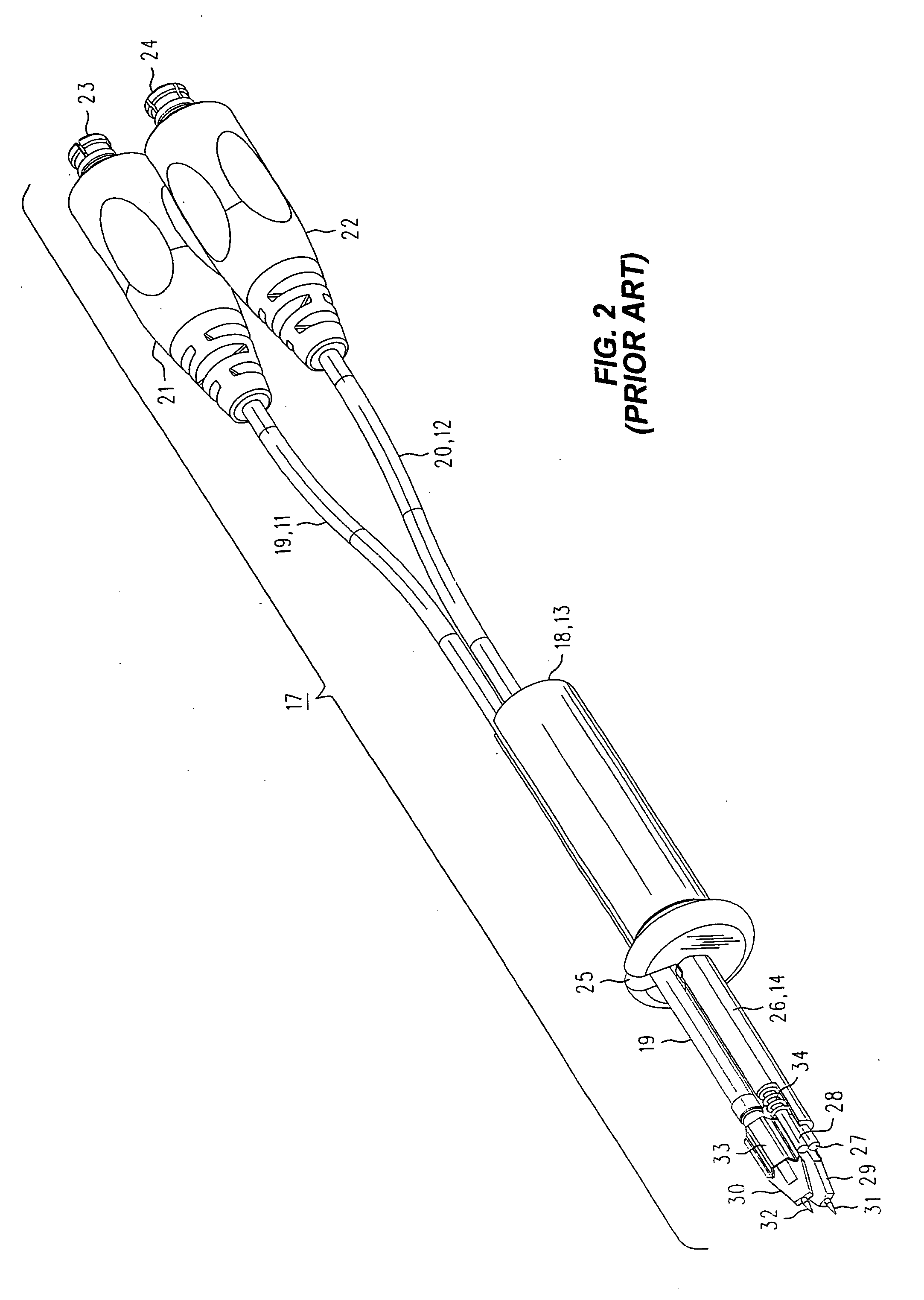
[0016] A pair of coaxial transmission lines (11,...


PUM


Abstract

A solution to the problem of broken micro-browser probe assemblies caused by the accidental application of excessive force is to manufacture the rods out of a material that resists forces found in normal usage and appears stiff, but that will abruptly deform harmlessly under less force than causes permanent damage to other elements of the micro-browser. The sudden deformation serves as a signal to the operator to stop being a gorilla. That leaves the problem of re-shaping the rod. A preferred solution is to use as the rod a Nitinol superelastic metal wire that automatically returns to its previous shape once the force causing deformation is removed. An alternate solution is to make the rod from a length of Nitinol “memory metal” wire that restores itself to a pre-set shape upon the application of mild heat, such as immersion in a cup of hot water from an office coffee machine. The small circuit board and its components are not bothered by the bath. In each case the diameter of the wire is selected to make the wire be strong enough to not deform under normal use, but to allow it to abruptly deform under less force than will damage the other elements in the micro-browser.

Description

BACKGROUND OF THE INVENTION [0001] Many types of electronic test equipment (e.g., oscilloscopes) often involve the probing of a circuit of interest with a hand held probe. The probe might acquire a single-ended signal or a differential one, and there mayor may not be a ground connection using a “flying lead” (a short length of flexible insulated wire with an alligator clip or other fastener at the free end). In particular, it is often necessary to probe the signals at two places on a PCB (Printed Circuit Board) that: (1) Are some arbitrary distance apart; (2) Are traces leading to surface mounted components with no leads around which a probe tip may be hooked, requiring that sharp probe tips be pressed into those traces; and (3) Carry signal that have high frequency components (say, in the Giga Hertz region). [0002] To accomplish these tasks a number of desirable properties of such a probe have been identified, and various designs have been offered. These desirable properties includ...

Claims


Application Information

Patent Timeline
Patent Type & Authority Applications(United States)
IPC IPC(8): G01B5/28G01R1/067G01R31/02
CPCG01R1/06794G01R1/06788
Inventor CANNON, JAMES E.
Owner AGILENT TECH INC
Why Eureka
Try Eureka