Contact assembly

a technology of contact assembly and assembly plate, which is applied in the direction of magnets, magnetic bodies, coupling device connections, etc., to achieve the effect of constant for

Inactive Publication Date: 2005-11-03
BAL SEAL ENG CO INC
View PDF15 Cites 39 Cited by
  • Summary
  • Abstract
  • Description
  • Claims
  • Application Information

AI Technical Summary

Benefits of technology

[0012] A contact coil spring in accordance with the present invention provides a nearly constant force over a wide deflection range greater than the variable distance, thus providing a constant force as wear occurs.

Problems solved by technology

Such variable distance is caused by misalignment due to initial assembly or through wear of the conductive rings.

Method used


Image

  • Contact assembly
  • Contact assembly
  • Contact assembly

Examples


Embodiment Construction

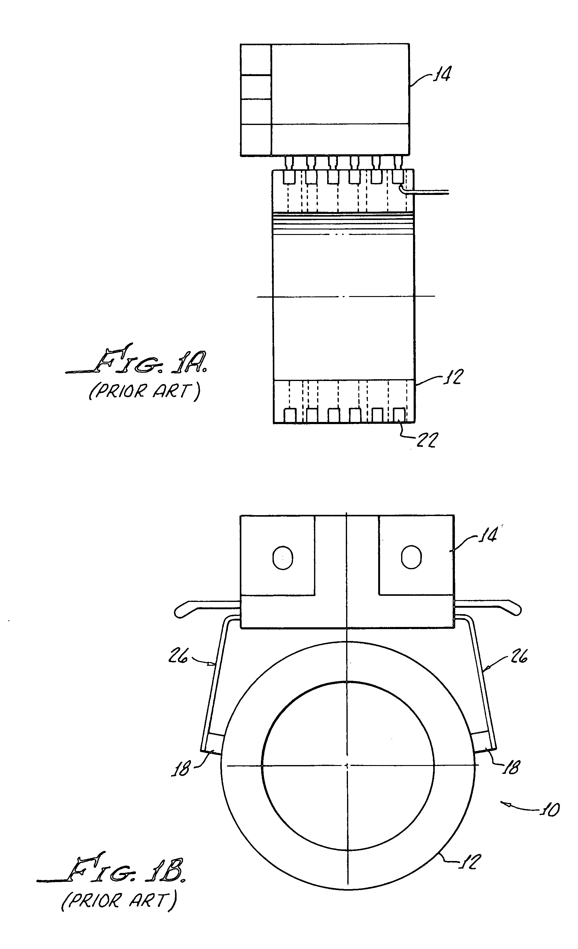
[0024] With reference to FIGS. 1A and 1B, there is shown, for comparison purposes, a conventional slip ring assembly 10 including a rotor 12, stator 14, a plurality of brushes, contacting slip rings 22 with the brushes 18 communicating with the stator 14 by means of a cantilever spring 26. As hereinabove noted, irregularities and wear often dictate a limited life of such an assembly.

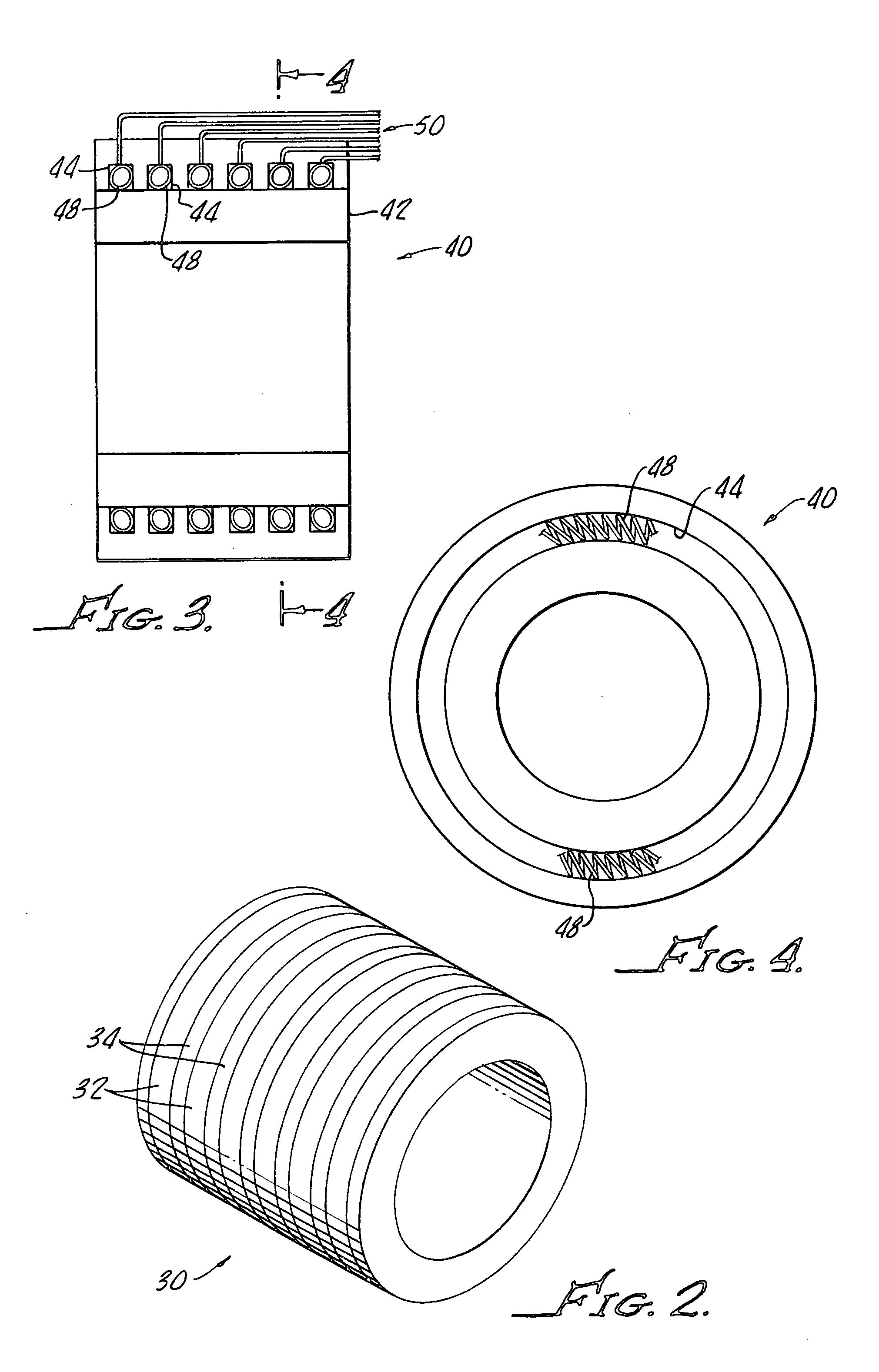
[0025] With reference to FIG. 2, there is shown a rotor 30 in accordance with the present invention which includes a plurality of spaced apart circumferential electrically conductive rings 32 separated by insulating strips 34.

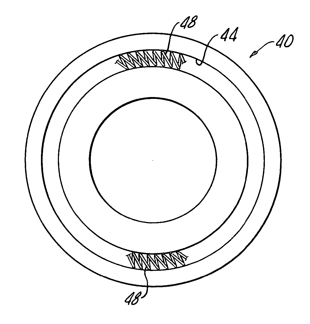
[0026] As shown in FIGS. 3 and 4, a stator 40 in accordance with the present invention generally includes a bore 42 therethrough for accepting the rotor 30 and includes a plurality of spaced apart grooves 44 alignable with the conducting rings 32 of the rotor 30 upon assembly.

[0027] Upon assembly, the grooves 44 are at a variable distance from the strips 32 due to irregularities,...


PUM

PropertyMeasurementUnit
circumferential electrically conductiveaaaaaaaaaa
constant forceaaaaaaaaaa
distanceaaaaaaaaaa

Abstract

A contact assembly for making electrical connection between coaxial members generally includes a rotor having a plurality of spaced apart circumferential electrically conductive rings, and a stator surrounding a rotor with a plurality of spaced apart grooves aligned with the plurality of rings at a variable distance therefrom. A plurality of circular canted-coil springs is provided with each spring being disposed and a corresponding groove providing constant force against a corresponding ring independent of the variable distance between the compression ring and the groove. A plurality of electrical leads is provided with each lead being electrically connected to a corresponding ring.

Description

[0001] The present application claims priority from the U.S. Provisional Patent Application Ser. No. 60 / 566,758 filed Apr. 29, 2004, which is to be incorporated herein in its entirety including all specification and drawings.[0002] The present invention generally relates to contact assemblies for transferring electrical current between a stationary and a rotating member. More particularly, the present invention is directed to improved electrical current and electrical signal transfer between a stationary and a rotating body. [0003] In order to provide electrical connection between a stator and a rotor, it has been conventional practice to provide an arrangement of brushes and contact rings, commonly known as slip rings, which are in continuous mutual sliding contact. [0004] There are various types of brushes, for example, cartridge, cantilever, and wire composites, as well as multi-fiber wire and others. All of these brush configurations are characterized by devices that provide an ...

Claims


Application Information

Patent Timeline
Patent Type & Authority Applications(United States)
IPC IPC(8): H01F7/08H01R13/187H01R24/58
CPCH01R13/187H01R2107/00H01R24/58
Inventor BALSELLS, PETER J.
Owner BAL SEAL ENG CO INC
Why Eureka
Try Eureka