
Print schedule control equipment, print schedule control method, and program therefor

Inactive Publication Date: 2005-11-03
CANON KK
View PDF14 Cites 100 Cited by
  • Summary
  • Abstract
  • Description
  • Claims
  • Application Information

AI Technical Summary

Benefits of technology

[0035] According to this invention, the print schedule control equipment becomes capable of registering schedules of the regular print job and the proof print job in a cooperation manner, which increases efficiency of scheduling work in the print processing.
[0037] Moreover, it becomes possible to control a printed matter of proof printing for a print job with a security setting; therefor, it is possible to increase the security and keep the print quality. Furthermore, it becomes possible to suppress an unnecessary output of proof printing.

Problems solved by technology

Here, the print schedule control equipment may further comprise reservation impossibility informing means for, when the schedule registering means cannot assign the first print job or when it cannot assign the second print job, informing that the reservation is impossible.

Method used


Image

  • Print schedule control equipment, print schedule control method, and program therefor
  • Print schedule control equipment, print schedule control method, and program therefor
  • Print schedule control equipment, print schedule control method, and program therefor

Examples


first embodiment

[0085] Hereafter, embodiments to which this invention can be applied will be described with reference to Figures will be described in detail. Incidentally, parts having the same functions are designated with the similar numerals and repeated explanation is omitted.

(Equipment Configuration)

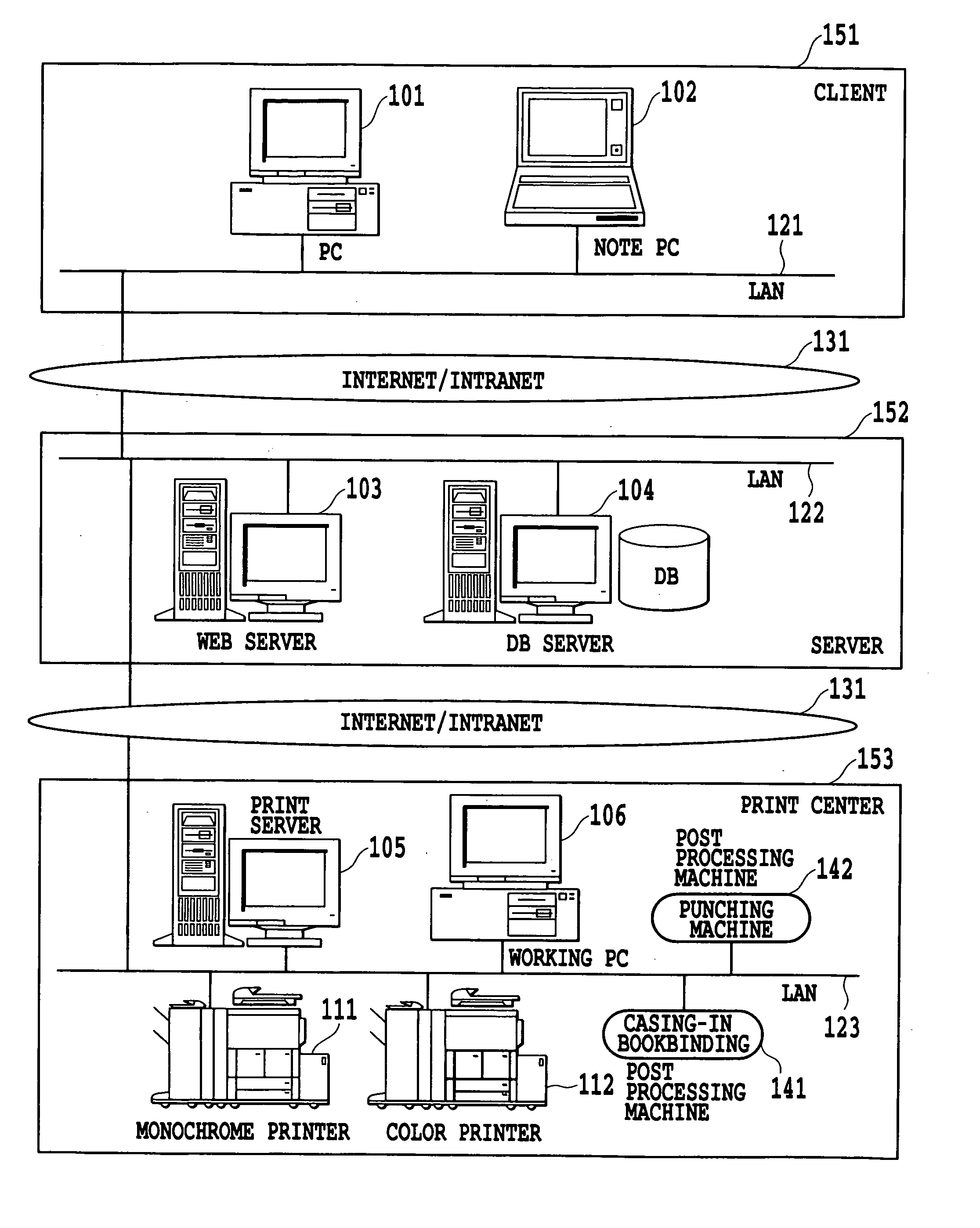
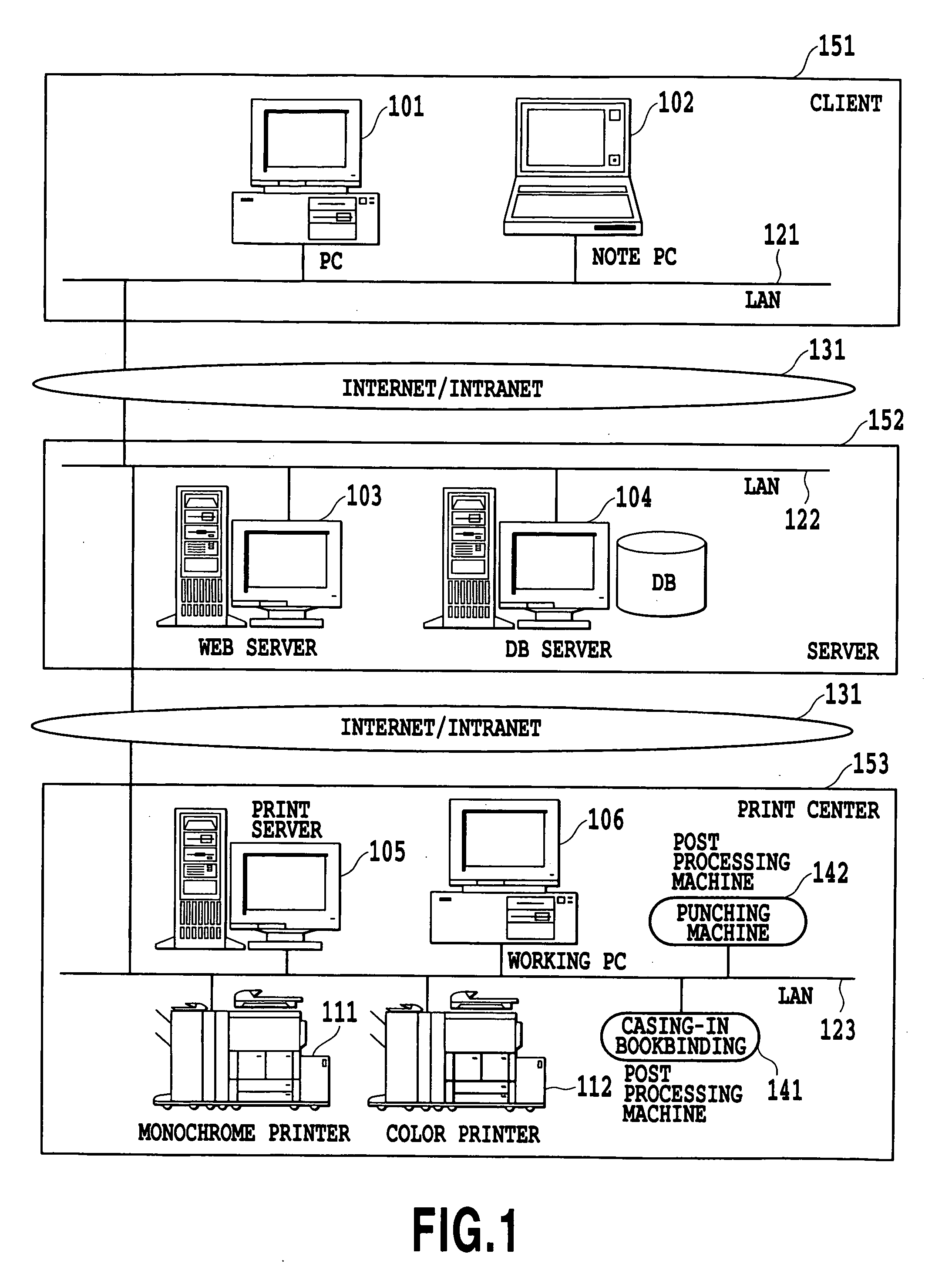
[0086]FIG. 1 is a diagram showing an overall configuration of a printing system of this embodiment. Note that environments of the total printing system in the following description is for making description of this embodiment easy to understand, and this invention is not limited to these environments.

[0087] In FIG. 1, clients 151 show a client of a note-book PC 102 on a normal user premise connected to the Internet and a client of a business PC 101 connected to in-house intranet installed in house.

[0088] Servers 152 shows an WEB server 103 that is a computer system for sending a print request and providing the contents of submitted manuscript and a DB (database) server 104 for saving a print r...

second embodiment

[0224] Next, a second embodiment to which this invention can be applied will be described in detail. The system configuration of the second embodiment is the same as that of the first embodiment.

[0225]FIG. 30 and FIG. 31 are illustrations showing processing of a printing system of the second embodiment that improves security by means of historical management of proof printing in a secure job. Note that the environments of the whole printing systems in the description below are for making description of this embodiment easy to understand and that this invention is not limited to these environments. FIG. 30 and FIG. 31 are views for explaining the print server 105 described above in FIG. 6 with simplification, and it must be understood that the print server 105 is equipped with several constituents whose description is omitted.

[0226] First, processing for forming historical information of proof printing will be described.

[0227] In Step 2105 in FIG. 21, the pertinent proof print job...


PUM


Abstract

This invention aims at conducting a scheduling work of print processing efficiently. A device scheduler refers to print job composition information registered in step control information of the step “printer reservation” of other print job (other order) in a workflow information table, and a schedule information table. The device scheduler searches both other print jobs (proof print jobs and regular print jobs) that a to-be-registered proof print job having a processing time of the proof print job described above affects and other print jobs (proof print jobs and regular print jobs) that affect the to-be-registered proof print job. The device scheduler determines whether the to-be-registered proof print job can be registered in a schedule (there is no search result in Step 2017 described above). When the registration is not possible, the device scheduler informs an operator of the result that automatic scheduling is impossible.

Description

BACKGROUND OF THE INVENTION [0001] 1. Field of the Invention [0002] The present invention relates to print schedule control equipment, a print schedule control method, and a program therefor. More specifically, this invention relates to print schedule control equipment for executing schedule control of a device used for a regular print job and a proof print job based on a request of printing, a print schedule control system therefor, a print schedule control method therefor, and a program therefor. [0003] 2. Description of the Related Art [0004] Conventionally, there are commercial printers (hereinafter, printing contractor) who generate printed matters on requests from customers of individual users and business enterprises. Each of such printing contractors run a business of receiving provision of print data (original copy) and instructions of a print format, the number of copies, a date of delivery, etc. from a customer, forming a printed matter, and delivering it to the customer....

Claims


Application Information

Patent Timeline
IPC IPC(8): B41J29/38G06F3/12G06F15/00G06Q50/00G06Q50/04H04N1/00H04N1/32
CPCG06F3/1262G06F3/1275H04N1/00236H04N1/00923H04N1/32502G06F3/1288G06F3/1208G06F3/1215G06F3/124G06F3/1241G06F3/1256H04N1/32545
Inventor NODA, AKIHIKO
Owner CANON KK
Learn More