Retrofocus type optical system

a technology of optical system and retrofocus, which is applied in the field of optical system, can solve the problems of chromatic aberration, chromatic aberration, and chromatic aberration, and achieve the effects of excellent environmental tolerance, favorable correction of various aberrations, and easy manufacturing

Inactive Publication Date: 2005-11-03
CANON KK
View PDF2 Cites 15 Cited by
  • Summary
  • Abstract
  • Description
  • Claims
  • Application Information

AI Technical Summary

Benefits of technology

[0013] The present invention has been made in view of the above-described difficulties in the conventional arrangements. An object of the present invention is to provide a retrofocus type optical system that achieves favorable corrections of various aberrations represented by chromatic aberration, is easy to manufacture and has excellent environmental tolerance.

Problems solved by technology

Problems the retrofocus type lens suffers in correcting aberrations are that barrel type distortion is liable to occur, that significant chromatic aberration of magnification (lateral chromatic aberration) is liable to occur, and that secondary spectrum of chromatic aberration of magnification tends to become large.
Since the refractive index of a low dispersion lens with extraordinary partial dispersion such as a fluorite lens is low, its position in an optical system is limited when used, or it is sometimes necessary to increase the number of the lenses in the system.
In addition, such lenses are very expensive and they cannot be used frequently in view of the cost.
Although diffraction optical elements have sufficient chromatic aberration correction effects, they suffer from the problem that diffracted light of useless diffraction orders different from the designed diffraction order becomes colored flare light that deteriorates imaging performance.
Although in some cases, a so-called laminated diffraction optical element composed of a plurality of blazed diffraction gratings stacked along the optical axis direction is used so as to concentrate energy on the designed diffraction order and to reduce useless diffracted light greatly, there still remains the problem that diffracted flare is generated when an object having high luminance is photographed.
However, diffraction efficiency of a diffraction optical element is extremely sensitive to the manufacturing accuracy, and a very high degree of precision in the metal mold and in the molding process is required.
This leads to high manufacturing costs.
The material disclosed in U.S. Pat. No. 4,913,535 is liquid, and a structure for sealing it is necessary and manufacturing thereof is not easy.
In addition, it suffers from the problem of changes in characteristics, such as refractive index and dispersion characteristics, depending on the temperature, namely, it does not have sufficient environmental tolerance.
In addition, that material suffers from the defect that it cannot achieve a sufficient chromatic aberration correction effect due to its relatively large Abbe constant, relatively small extraordinary partial dispersion and absence of interface with the air.

Method used


Image

  • Retrofocus type optical system
  • Retrofocus type optical system
  • Retrofocus type optical system

Examples


embodiment 1

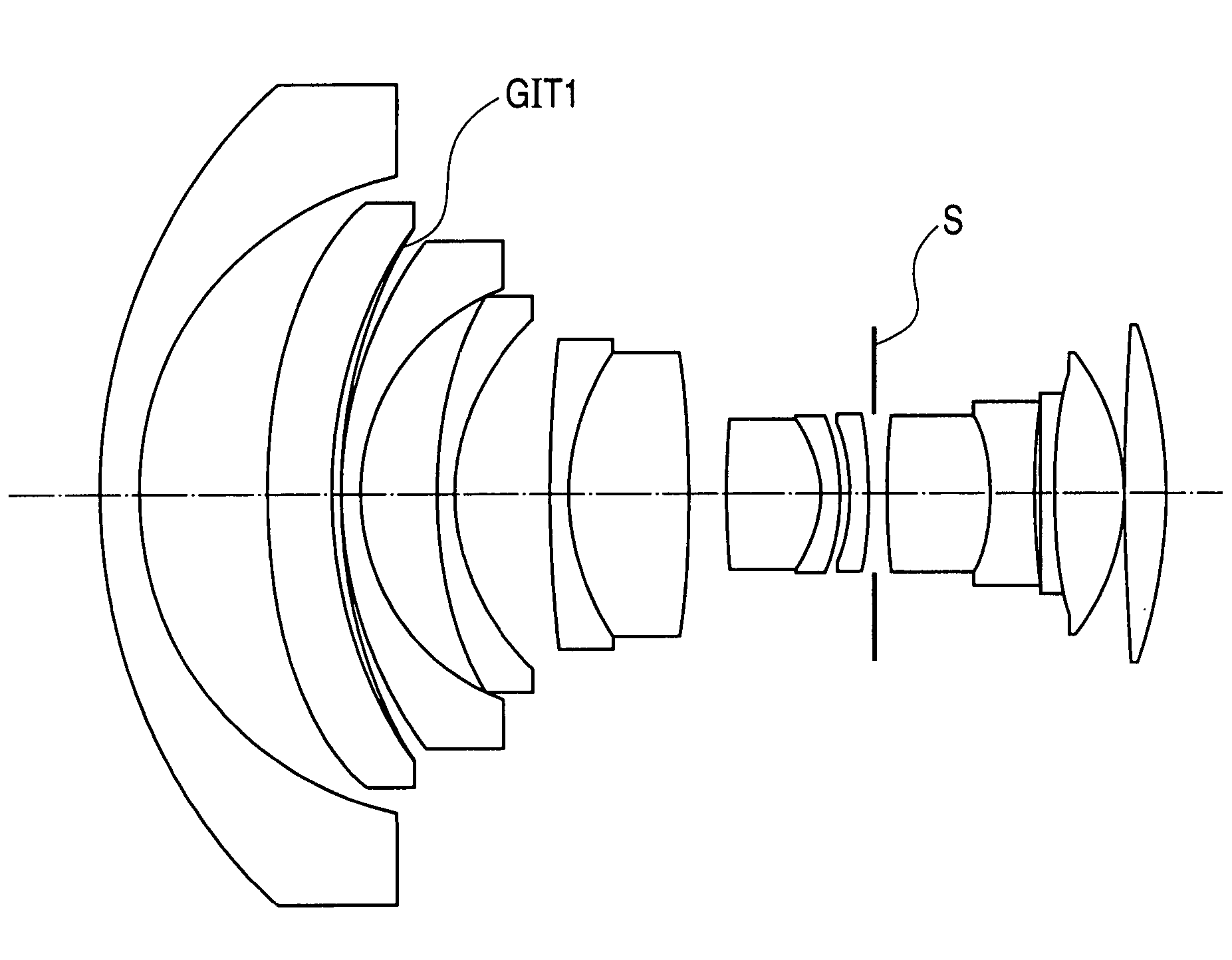
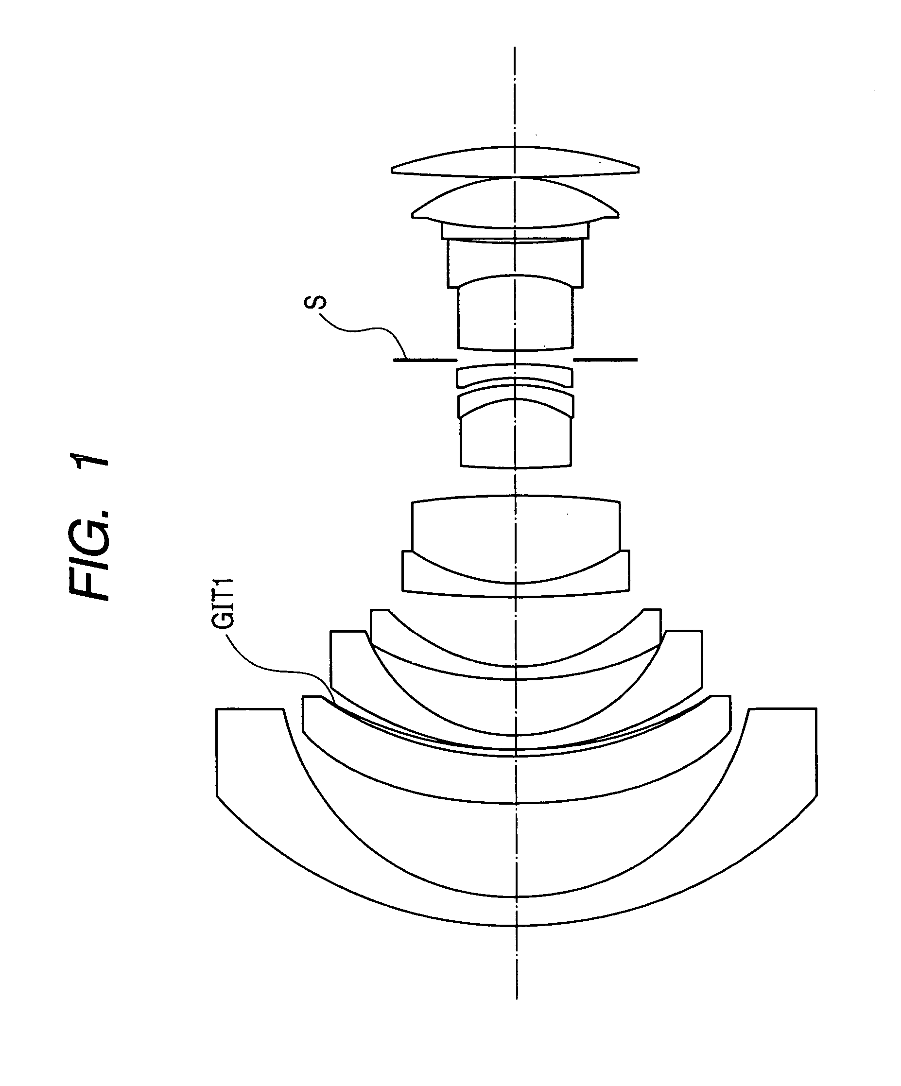
[0090] In the optical system of numerical embodiment 1, the lens (layer) made of the mixture containing ITO fine particles is employed in the object side portion, in which the height, from the optical axis, of the path of the paraxial chief ray is relatively high. In addition, the lens (layer) GIT1 made of the mixture containing ITO fine particles is designed to have a positive refractive power to mainly correct chromatic aberration of magnification, so that a retrofocus type optical system in which chromatic aberration of magnification is excellently corrected is realized.

[0091]FIG. 3 is a cross sectional view showing an optical system according to numerical embodiment 2, in which a lens (or layer) made of a mixture containing ITO fine particles is employed in a wide angle zoom lens with the focal length range of 17 mm to 40 mm. In this example, acrylic in which ITO fine particles are mixed at a proportion of 20% is used. In FIG. 3, reference sign GIT2 designates the lens (layer) m...

embodiment 2

[0092] In the optical system of numerical embodiment 2, the lens (layer) made of the mixture containing ITO fine particles is employed on the image side of the aperture stop S, in which the height, from the optical axis, of the path of the paraxial chief ray is relatively high. In addition, the lens (layer) GIT2 made of the mixture containing ITO fine particles is designed to have a negative refractive power to intensively correct chromatic aberration of magnification, so that a retrofocus type optical system in which chromatic aberration of magnification is excellently corrected is realized.

[0093]FIG. 5 is a cross sectional view showing an optical system according to numerical embodiment 3, in which a lens (or layer) made of a mixture containing ITO fine particles is employed in a wide angle zoom lens with the focal length range of 20 mm to 35 mm. In this example, a resin material for replicas in which ITO fine particles are mixed at a proportion of 20% is used. In FIG. 5, referenc...

embodiment 3

[0094] In the optical system of numerical embodiment 3, the lens (layer) made of the mixture containing ITO fine particles is employed on the image side of the aperture stop S, in which the height, from the optical axis, of the path of the paraxial chief ray is relatively high. In addition, the lens (layer) GIT2 made of the mixture containing ITO fine particles is designed to have a negative refractive power to intensively correct chromatic aberration of magnification, so that a retrofocus type optical system in which chromatic aberration of magnification is excellently corrected is realized.

[0095]FIG. 7 is a cross sectional view showing an optical system according to numerical embodiment 4, in which a lens (or layer) made of a mixture containing ITO fine particles is employed in a wide angle zoom lens with the focal length range of 22 mm to 55 mm. In this example, a resin material for replicas in which ITO fine particles are mixed at a proportion of 20% is used. In FIG. 7, referenc...


PUM


Abstract

Provided is a retrofocus type optical system including a lens or a layer made of a material satisfying the following conditions of the Abbe constant νd and partial dispersion ratios θgd and θgF,
νd<30,
θgd<−3.333×10⁻³·νd+1.40,
θgF<−2.615−10−3·νd+0.67.
In the case that this layer is disposed on the front side of the aperture stop, the layer is designed to have a positive refractive power, and in the case that the layer is disposed on the rear side of the aperture stop, the layer is designed to have a negative refractive index.

Description

BACKGROUND OF THE INVENTION [0001] 1. Field of the Invention [0002] The present invention relates to an optical system in which an optical material with extraordinary partial dispersion is used, or an optical system that is suitable for an image taking optical system of a silver halide film camera, a digital still camera or a video camera, or a projection optical system of a liquid crystal projector. [0003] 2. Description of the Related Art [0004] Conventionally, a retrofocus type lens has been known as a type of lens having a short focal length and a long back focus. In the retrofocus type lens, a long back focus can be realized by arranging a lens unit having negative refractive power as a whole in the front side (i.e. the magnification side: the object side in the case of a image taking optical system of camera and or the like, or the screen side in the case of a projection optical system of a projector or the like) of the optical system and arranging a lens unit having a positiv...

Claims


Application Information

Patent Timeline
Patent Type & Authority Applications(United States)
IPC IPC(8): G02B3/00G02B27/00
CPCG02B27/0012
Inventor ENDO, HIROSHI
Owner CANON KK
Why Eureka
Try Eureka