Protection devices and methods for preventing the flow of undesirable differential mode transients

a protection device and differential mode technology, applied in the direction of overvoltage protection resistors, emergency protective arrangements for limiting excess voltage/current, and arrangements responsive to excess voltage, etc., can solve the problems of damage to equipment, damage to isolation devices, and risk of circuitry damag

Active Publication Date: 2005-11-03
BOURNS INC
View PDF5 Cites 27 Cited by
  • Summary
  • Abstract
  • Description
  • Claims
  • Application Information

AI Technical Summary

Problems solved by technology

Wherever electronic circuitry is coupled to an external cable run, a risk of damage to the circuitry, due to the transmission of transient overvoltages by the cable run, may occur.
The surge current may damage the isolation device and may also damage the equipment that is intended to be protected.
Consequently, while an isolation transformer provides a good measure of protection from common mode transients, it does not provide protection from differential mode surges.
For example, in the event of a voltage transient occurring at the RX+ pin but not on the RX− pin, that transient most likely will be transmitted across the isolation transformer and may damage processing chip 24.

Method used


Image

  • Protection devices and methods for preventing the flow of undesirable differential mode transients
  • Protection devices and methods for preventing the flow of undesirable differential mode transients
  • Protection devices and methods for preventing the flow of undesirable differential mode transients

Examples


Embodiment Construction

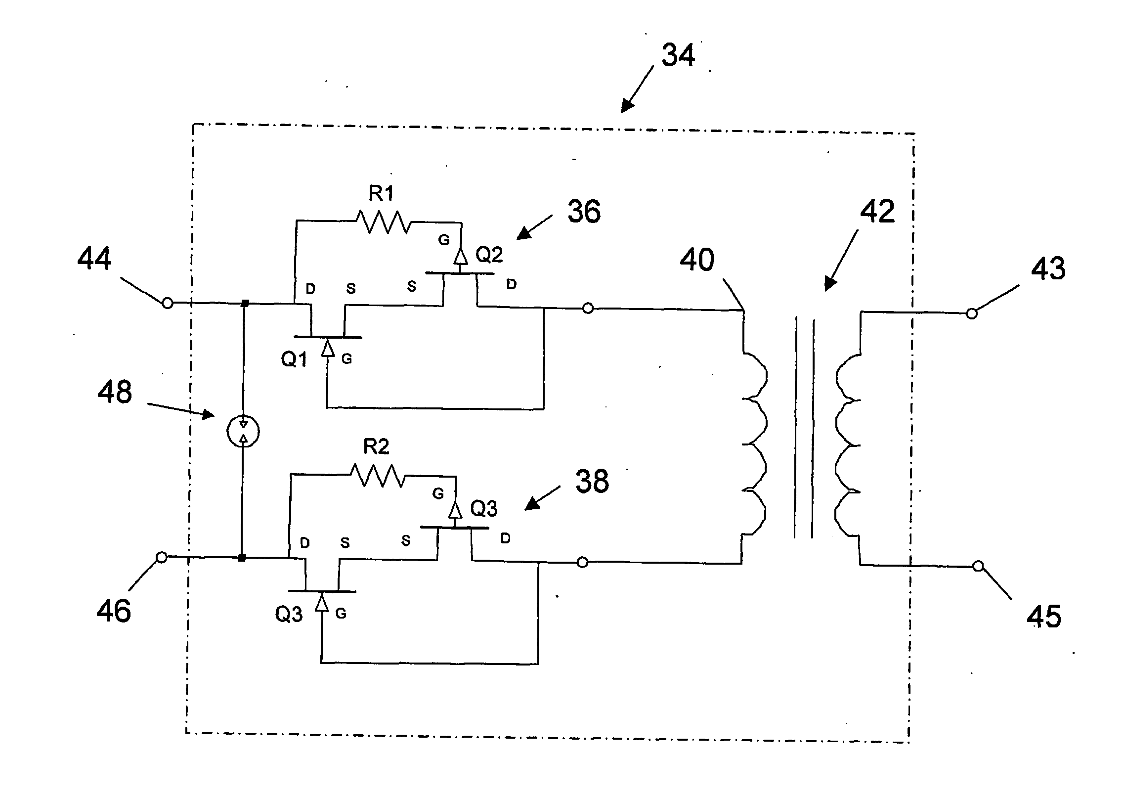
[0028] Referring now to FIG. 5, an isolation module 34 according to an embodiment is depicted. Isolation module 34 includes a common mode isolation device 42, which comprises a transformer. It is understood that common mode isolation device 42 could instead be some other common mode isolation device such as an opto-isolator. Isolation module 34 includes two identical series connected unipolar transient blocking units (TBUs) 36 and 38 connected at respective sides of primary coil 40 of transformer 42.

[0029] A TBU is a transistor device configured to open-circuit once the current through it reaches a certain predetermined trigger level. TBU 36 consists of two depletion mode FETs being N-channel FET Q1 and P-channel FET Q2. Q1 and Q2 are connected with their conduction paths in series. The gate electrode of transistor Q1 is coupled to the drain electrode of transistor Q2. The source electrodes of Q1 and Q2 are coupled to each other and the drain electrode of transistor Q1 is coupled t...


PUM


Abstract

A differential mode surge protection apparatus includes first and second solid state protection devices in series between respective input and output connection points. The apparatus may be provided in conjunction with a common mode protection apparatus such as an isolation transformer. Alternatively, the apparatus may be provided integrated into a single miniaturized protection package. In a preferred embodiment, the apparatus includes a surge arrestor arranged to supplement protection conferred by the first and second solid state protection devices. The surge arrestor is capable of being triggered prior to breakdown of either the first or second solid state protection devices. The apparatus may be incorporated into digital processing cards such as LAN cards and also into cables to conveniently provide differential mode protection.

Description

FIELD OF THE INVENTION [0001] The present invention relates to electrical surge protection devices, and more particularly to protection devices and methods for preventing the flow of undesirable differential mode transients. BACKGROUND TO THE INVENTION [0002] Wherever electronic circuitry is coupled to an external cable run, a risk of damage to the circuitry, due to the transmission of transient overvoltages by the cable run, may occur. Such overvoltages may be due to any one of several factors. For example, lightning, electrostatic discharge, or malfunction of equipment at a remote end of the cable may be responsible. Several techniques exist for isolating circuitry from potentially damaging surges. These include, inductive coupling as shown in FIG. 1, capacitive coupling, and opto-isolation as shown in FIG. 2. Isolation transformers are usually used to implement inductive coupling. [0003]FIG. 1 is a schematic diagram of a typical arrangement whereby a cable including a pair of con...

Claims


Application Information

Patent Timeline
Patent Type & Authority Applications(United States)
IPC IPC(8): H02H9/00H02H9/02H02H9/06
CPCH02H9/005H04M3/18H02H9/06H02H9/025
Inventor HARRIS, RICHARD
Owner BOURNS INC
Why Eureka
Try Eureka