
Wireless LAN system

a lan system and wireless technology, applied in the field of wireless lan systems, can solve the problems of considerable deterioration in communication speed between legacy terminals and ht terminals, and achieve the effect of preventing deterioration of throughput and deterioration of throughpu

Active Publication Date: 2005-11-03
SHARP KK
View PDF3 Cites 27 Cited by
  • Summary
  • Abstract
  • Description
  • Claims
  • Application Information

AI Technical Summary

Benefits of technology

[0016] The above-mentioned circumstances being taken into account, the present invention has been developed and an object thereof is to provide a high-speed wireless LAN system capable of avoiding a collision of packets and maintaining the original transmission speed.
[0049] According to the present invention, since the occupation signal has the compatibility with the first radio communication system, it is possible to make the first radio communication system recognize the occupation signal and notify the occupation by the second radio communication system. Moreover, since communication is performed in the second radio communication system after the occupation signal is transmitted using every frequency in the second frequency band, it is possible to perform communication in the second radio communication system while making the first radio communication system suppress transmission and occupying the radio medium. Due to this, a collision of packets can be avoided and the deterioration of throughput can be prevented. As a result, it becomes possible to perform communication at the original transmission speed in the second radio communication system.

Problems solved by technology

As a result, the throughput is deteriorated.
In other words, there arises a problem of considerable deterioration in communication speed between legacy terminals and between HT terminals.

Method used


Image

  • Wireless LAN system
  • Wireless LAN system
  • Wireless LAN system

Examples


first embodiment

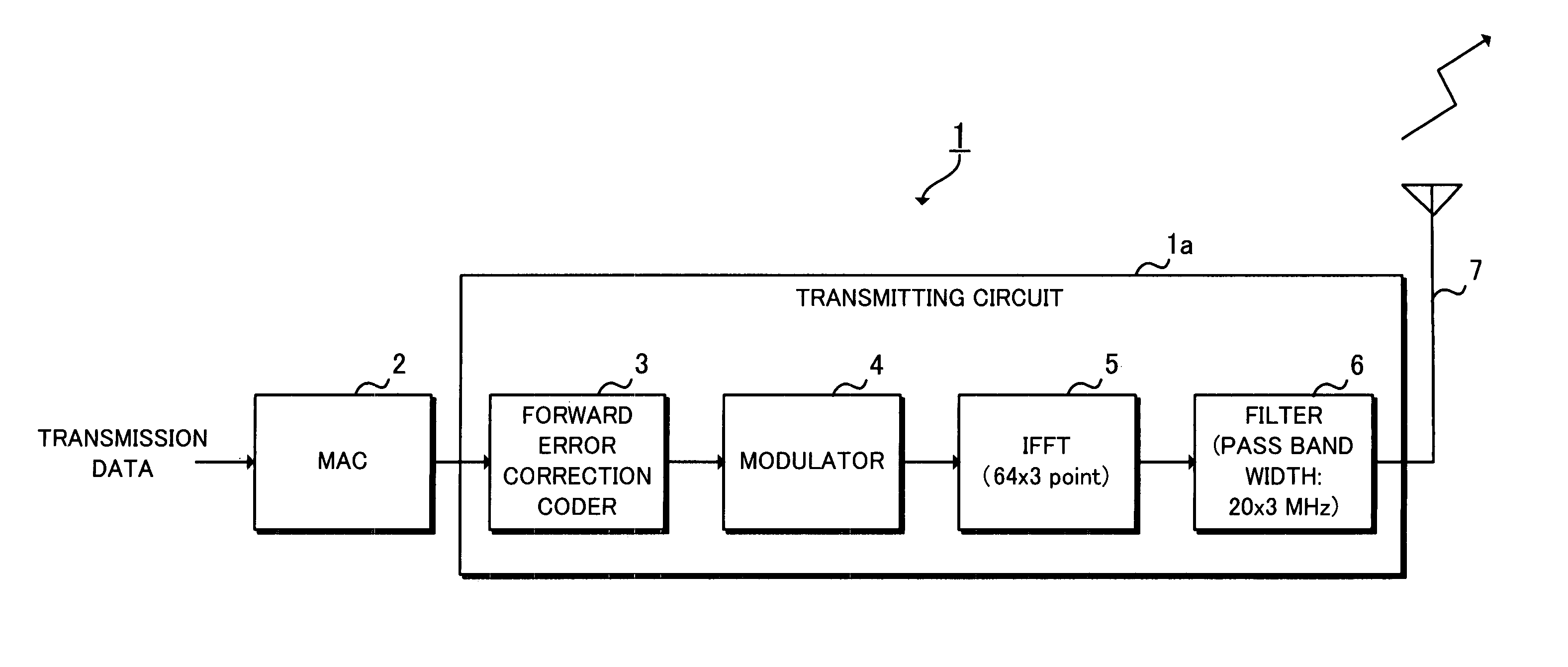
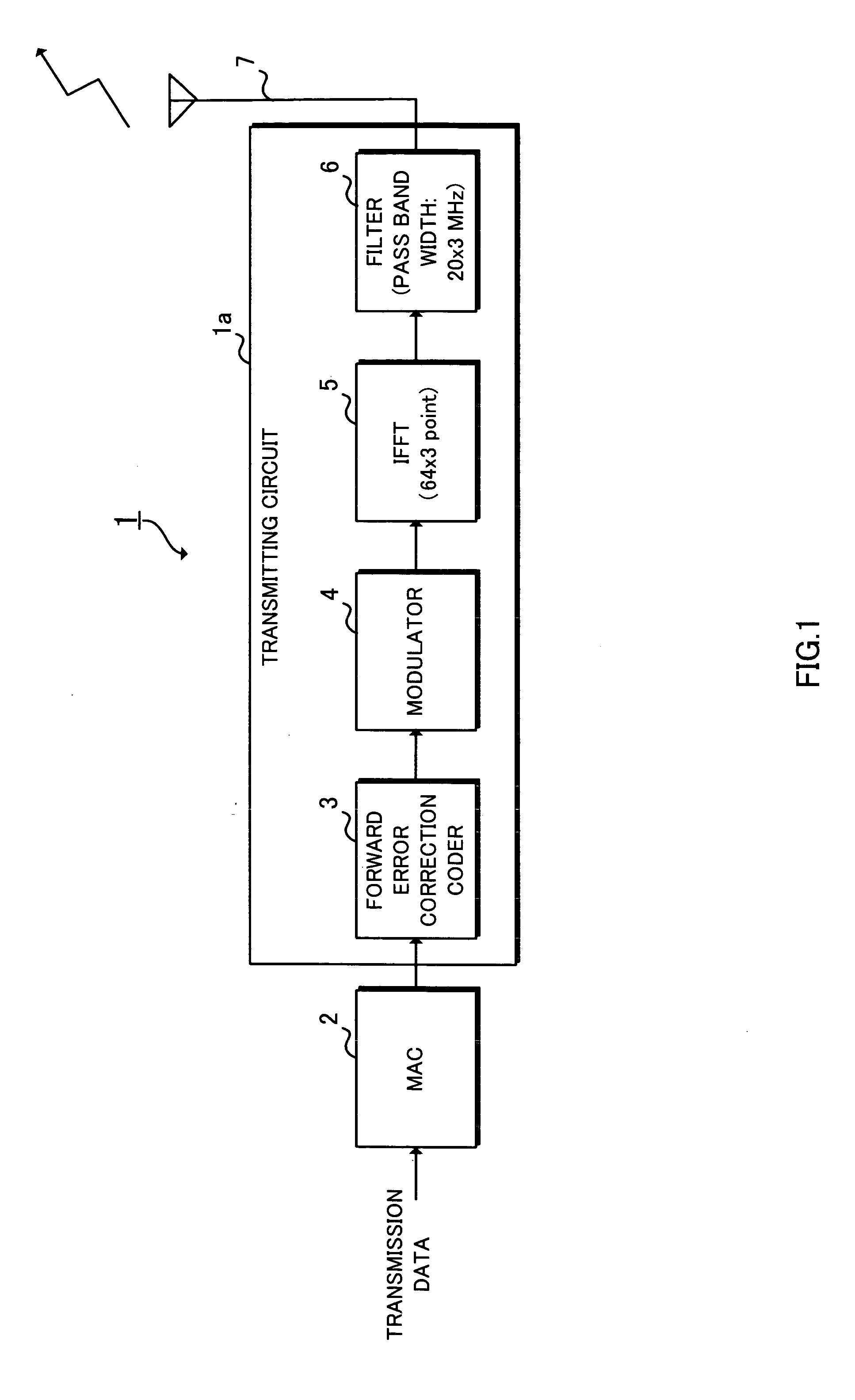
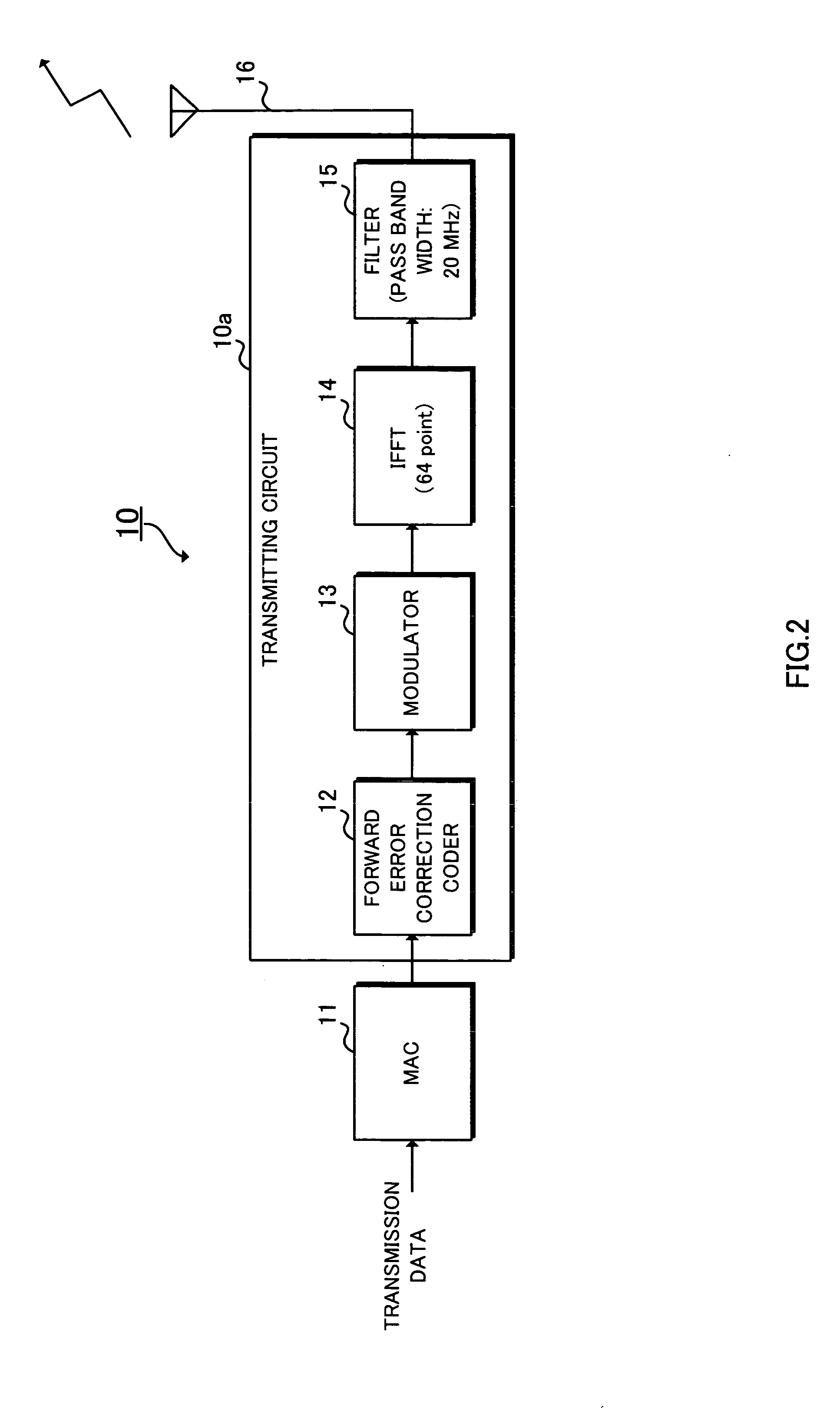
[0099]FIG. 1 a block diagram showing a configuration of a transmitter of an HTSTA applied to a wireless LAN system according to a first embodiment and FIG. 2 is a block diagram showing a configuration of a transmitter of a legacy STA applied to a legacy wireless LAN system. In FIG. 1, in a transmitter 1 of the HTSTA, transmission data are inputted in an MAC circuit 2 and a transmitting / receiving method of a frame, which is a transmission / reception unit of data, a frame format, etc., are defined. An Forward Error Correction Coder 3 performs error correction coding for a signal inputted from the MAC circuit 2. A modulator 4 performs modulation such as BPSK (Binary PSK) or QPSK (Quadrature PSK) for a signal inputted from the Forward Error Correction Coder 3. An IFFT circuit 5 converts a signal inputted from the modulator 4 from a frequency signal into a time signal. A filter circuit 6 allows only the signals in a desired band among signals inputted from the IFFT circuit 5 to pass for o...

second embodiment

[0119] In a wireless LAN system according to a second embodiment, as in the wireless LAN system according to the first embodiment, a signal for notifying that the radio medium is occupied is transmitted and the period of time during which an HT sequence is performed is occupied logically with respect to a legacy terminal. Here, in the case where a legacy AP and an HTAP coexist in the same frequency band, as in the first embodiment, transmission of both the legacy beacon and the legacy CTS prior to the HT sequence leads to an increase in overhead. Therefore, in the second embodiment, the legacy beacon is not transmitted but the legacy CTS and the HT sequence (HT beacon, HT data) are transmitted in this order, as shown in FIG. 18. In this case also, as shown in FIG. 19, the legacy CF-poll may be used instead of the legacy CTS.

[0120] As shown in FIG. 20, the normal MAC frame that specifies the period to protect in the duration may be used. However, as explained in FIG. 14 and FIG. 15,...

third embodiment

[0122] In a wireless LAN system according to a third embodiment, coexistence of the HT terminal and the legacy terminal is realized. In other words, the HT terminal occupies a part of period of the radio medium but does not occupy another part, thereby the coexistence with the legacy terminal is realized.

[0123] In the third embodiment, the time of duration in a legacy MAC frame transmitted by the HT terminal is set to x % (x % is equal to or less than 100%) of the interval from the end of the legacy MAC frame to the next beacon. It is possible to adjust the ratio of communication time of the HT terminal to that of the legacy terminal in accordance with this ratio (the ratio of the part of the radio medium occupied by the HT terminal to the whole). FIG. 22 shows a state in which the HT terminal occupies 100% of the interval from the end of the legacy MAC frame to the next beacon. FIG. 23 shows a state in which the HT terminal occupies, for example, 70% of the interval from the end o...


PUM


Abstract

A high-speed wireless LAN system capable of avoiding a collision of packets and maintaining the original transmission speed is provided. A transmitter is applied to an HT terminal using a second frequency band wider than a first frequency band used by a legacy terminal, in which an HT sequence is started after a legacy beacon as an occupation signal and a legacy CTS are transmitted using every frequency in the second frequency band. Due to this, an NAV is set at the legacy terminal and packets are no longer transmitted from the legacy terminal. As a result, a collision of packets is avoided and it becomes possible to perform communication between HT terminals at the original transmission speed.

Description

BACKGROUND OF THE INVENTION [0001] 1. Field of the Invention [0002] The present invention relates to a wireless LAN system for transmitting a signal for occupying a radio medium. [0003] 2. Related Background of the Invention [0004] Conventionally, a wireless LAN system in compliance with the IEEE 802.11a (hereinafter, referred to simply as “11a”) standard having a maximum transmission speed of 54 Mbit / s is proposed, in addition to a wireless LAN system in compliance with the IEEE 802.11b (hereinafter, referred to simply as “11b”) standard having a transmission speed of 11 Mbit / s. Moreover, the IEEE 802.11g (hereinafter, referred to simply as “11g”) standard having both features of the IEEE 802.11b and IEEE 802.11a is proposed. Hereinafter, an access point and a station in a wireless LAN system in compliance with these standards are referred to as a “legacy terminal”, a legacy access point as a “legacy AP”, and a legacy station as a “legacy STA.”[0005] In recent years, a transmission...

Claims


Application Information

Patent Timeline
IPC IPC(8): H04L12/28H04W16/14H04W74/04H04W84/12
CPCH04W16/14H04W84/12H04W74/04
Inventor IMAMURA, KIMIHIKONAKASHIMA, DAIICHIRO
Owner SHARP KK
Learn More