
Variable packet-size backplanes for switching and routing systems

a backplane and packet-size technology, applied in the field of high-throughput and/or multi-service (multi-protocol) switches and routers, can solve the problem of limiting the effect of packet-size distribution on system resource allocation, and achieve the effect of efficient operation

Active Publication Date: 2005-11-03
RPX CORP
View PDF12 Cites 35 Cited by
  • Summary
  • Abstract
  • Description
  • Claims
  • Application Information

AI Technical Summary

Benefits of technology

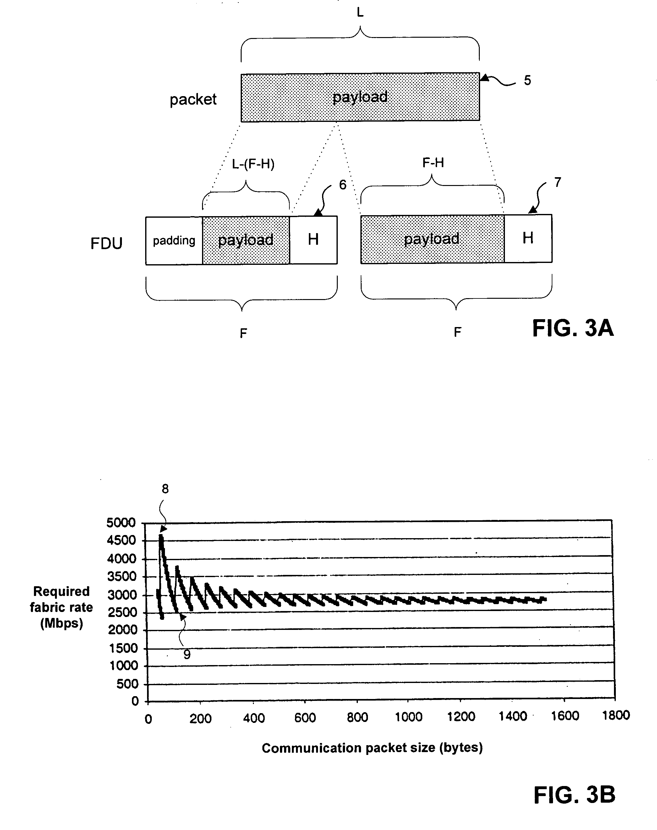
[0009] The present invention overcomes these identified prior-art problems, providing methods for switch and / or router systems that forward communication data packets through the system switch fabric in variably-sized packets known as fabric data units (FDU). These methods allow switches and routers to perform efficiently in an environment having variable, and usually unpredictable, communication data packet sizes. Accordingly, the switches and routers of this invention can efficiently operate in multi-service or multi-protocol applications, and specifically, in applications where both internet protocol (IP) and asynchronous transfer mode (ATM) packet flows must be handled.
[0010] These methods also preferably include control functions for selecting queued communication data packets to forward through the systems that provide controlled and fair use of switch resources. These methods, known as schedulers, can limit the effect of packet-size distribution on system resource allocation. Preferred switch and / or router systems have one or more ingress elements for receiving communication data packets, one or more egress elements for transmitting communication data packets, and a fully-connected switch fabric. Implementation of the methods of this invention is preferably distributed among the ingress and egress elements so that a central control element is optional and not required.
[0011] In a first preferred embodiment, this invention includes a system for switching or routing communication data packets having: (a) a plurality of ingress elements linked to a plurality of egress elements by a switch fabric, wherein the ingress elements receive data packets and the egress elements transmit data packets, and wherein the switch fabric transmits data between ingress and egress elements in fabric data units (FDU) having sizes varying from a minimum size to a maximum size; and (b) one or more control elements for performing repeatedly the steps of selecting a data packet received by an ingress element; and forwarding the selected data packet to an egress element in one or more variably-sized FDUs.

Problems solved by technology

These methods, known as schedulers, can limit the effect of packet-size distribution on system resource allocation.

Method used


Image

  • Variable packet-size backplanes for switching and routing systems
  • Variable packet-size backplanes for switching and routing systems
  • Variable packet-size backplanes for switching and routing systems

Examples


Embodiment Construction

[0021] Preferred embodiments of the methods and systems of this invention are described herein.

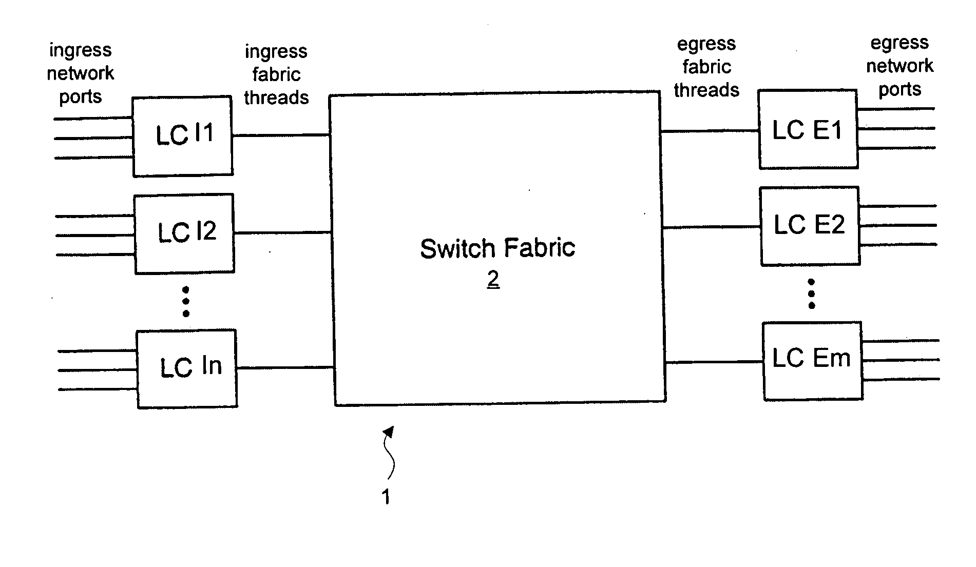
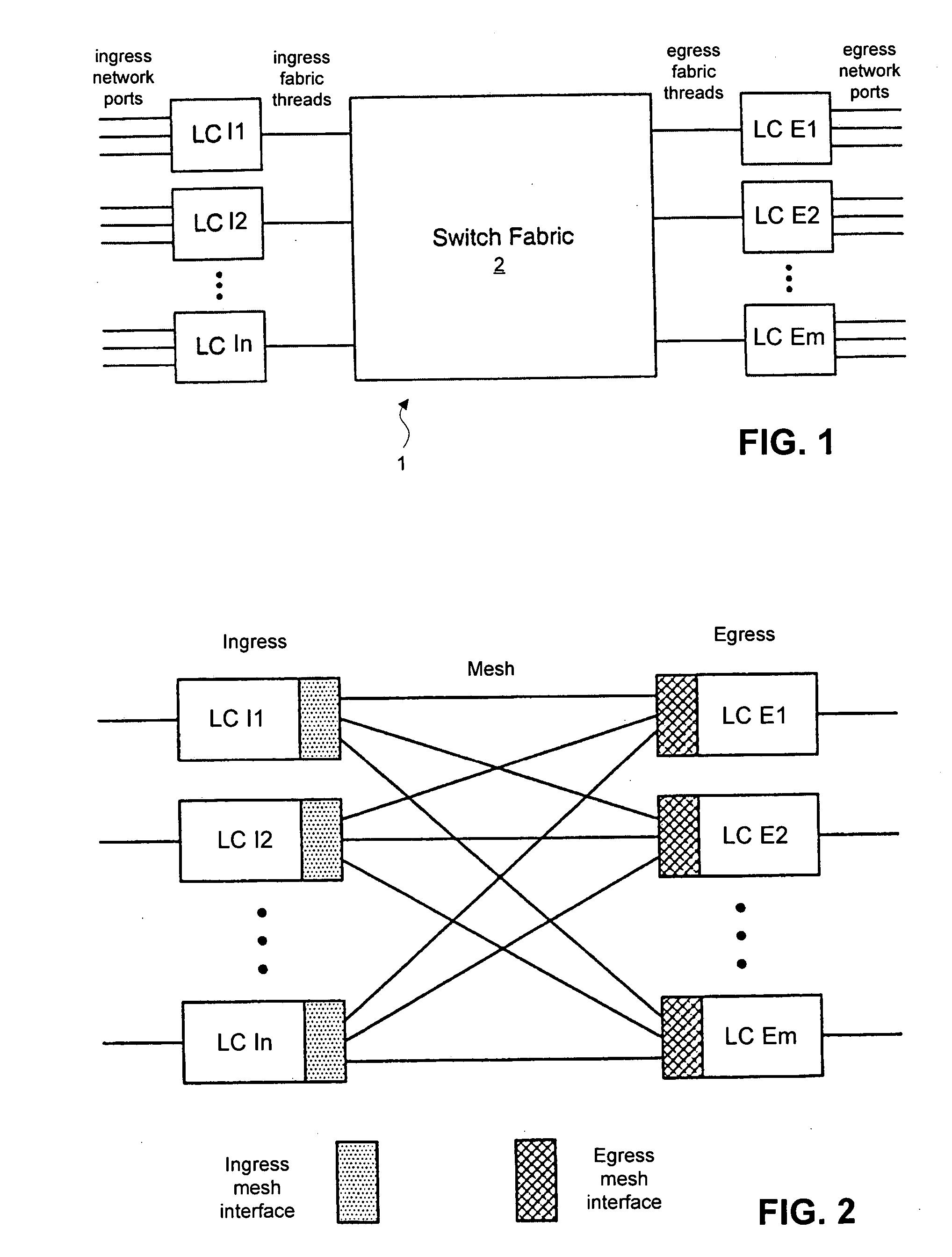
[0022]FIG. 1 generally illustrates a switch / router architecture suitable for the present invention. Switch / router 1 includes ingress elements, namely ingress line cards LC 11 to LC In, egress elements, namely egress line cards LC E1 to LC Em, and switch fabric 2 (also known herein as a “backplane”). Each ingress line card provides one or more input ports for connecting network communication links and one or more output ports connecting switch fabric links (threads). Each egress line cards provides one or more input ports for connecting switch fabric links and one or more output ports for connecting network communication links. Both types of line cards usually include processing and memory functions suitable for managing the flow of data packets from ingress elements to proper egress elements through the switch fabric. Data is transmitted from ingress to egress elements as fabric data unit...


PUM


Abstract

The present invention provides switches and routers, preferably with fully-connected mesh fabrics, that transmit data through the switch fabric in variable-size data units. Variable-size data units allow switches and routers to provide throughputs close to hardware capabilities, eliminating the need for over-capacity hardware in the switch fabric and other components. Along with variably-size data units, preferred embodiments of this invention include scheduling methods that provide fair allocation of pre-determined bandwidths to different protocols, to different classes of service within protocols, and to different resources within the switch by use of certain weighted, fair scheduling methods. The switches and routers of this invention are particularly directed to multi-protocol, high-throughput communication applications, but may have wide applicability in systems generally where data packets are switched or routed.

Description

[0001] This application incorporates by reference in their entireties and for all purposes the following patent applications, all of which are owned or subject to a right of assignment to the assignee of the present application and all of which were filed concurrently together with the present application: (1) the application titled “SYSTEMS AND METHODS IMPLEMENTING 1+1 AND N:1 LINE CARD REDUNDANCY”, by Bitar et al. and identified by attorney docket no. BITAR 6-10 (Ser. No. ______) (hereafter, the “Redundancy application”); (2) the application titled “METHODS AND SYSTEMS FOR EFFICIENT MULTICAST ACROSS A MESH BACKPLANE”, by Bitar et al. and identified by attorney docket no. BITAR 7-11-1 (Ser. No. ______) (hereafter, the “Multicast application”); (3) the application titled “A UNIFIED SCHEDULING AND QUEUEING ARCHITECTURE FOR A MULTISERVICE SWITCH”, by Bitar et al. and identified by attorney docket no. BITAR 4-8-2 (Ser. No. ______) (hereafter, the “Scheduler application”); and (4) the a...

Claims


Application Information

Patent Timeline
IPC IPC(8): H04L12/28H04L12/56
CPCH04L49/602H04L49/608H04L49/606
Inventor BITAR, NABIL N.TO, PHILIPHOCH, THOMAS A.
Owner RPX CORP
Learn More