

Cantilevered micro-electromechanical switch array
a micro-electromechanical switch array and cantilever technology, applied in relays, optical elements, instruments, etc., can solve the problems of inoperable structures, large arrays of switching elements, and inability to consider the creation of large switching arrays, etc., and achieve the effect of low cos
- Summary
- Abstract
- Description
- Claims
- Application Information
AI Technical Summary
Benefits of technology
Problems solved by technology
Method used
Image

Examples
Embodiment Construction
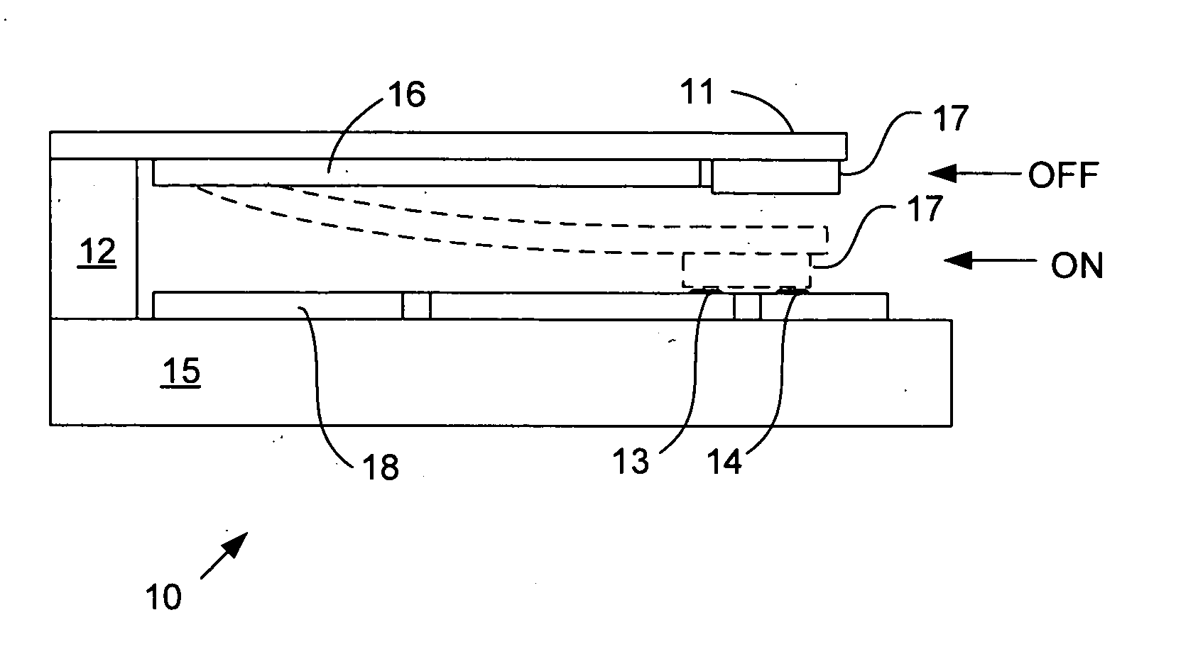
[0010] Embodiments of the present invention provide MEMS having suspended or structures or cantilevered platforms that are manufactured using low cost techniques on plastic substrates or other flexible materials.
[0011] Embodiments of the present invention include a latching switch. Preferably, the switch is a cantilever structure, which is sculpted from a continuous sheet of material. Further, in accordance with the present invention, the sculpted cantilever structure can be manufactured with high yield so it is feasible to form large area arrays of latching switches.
[0012] The foregoing and additional features and advantages of this invention will become apparent from the detailed description and review of the associated drawing figures that follow.
BRIEF DESCRIPTION OF THE DRAWINGS
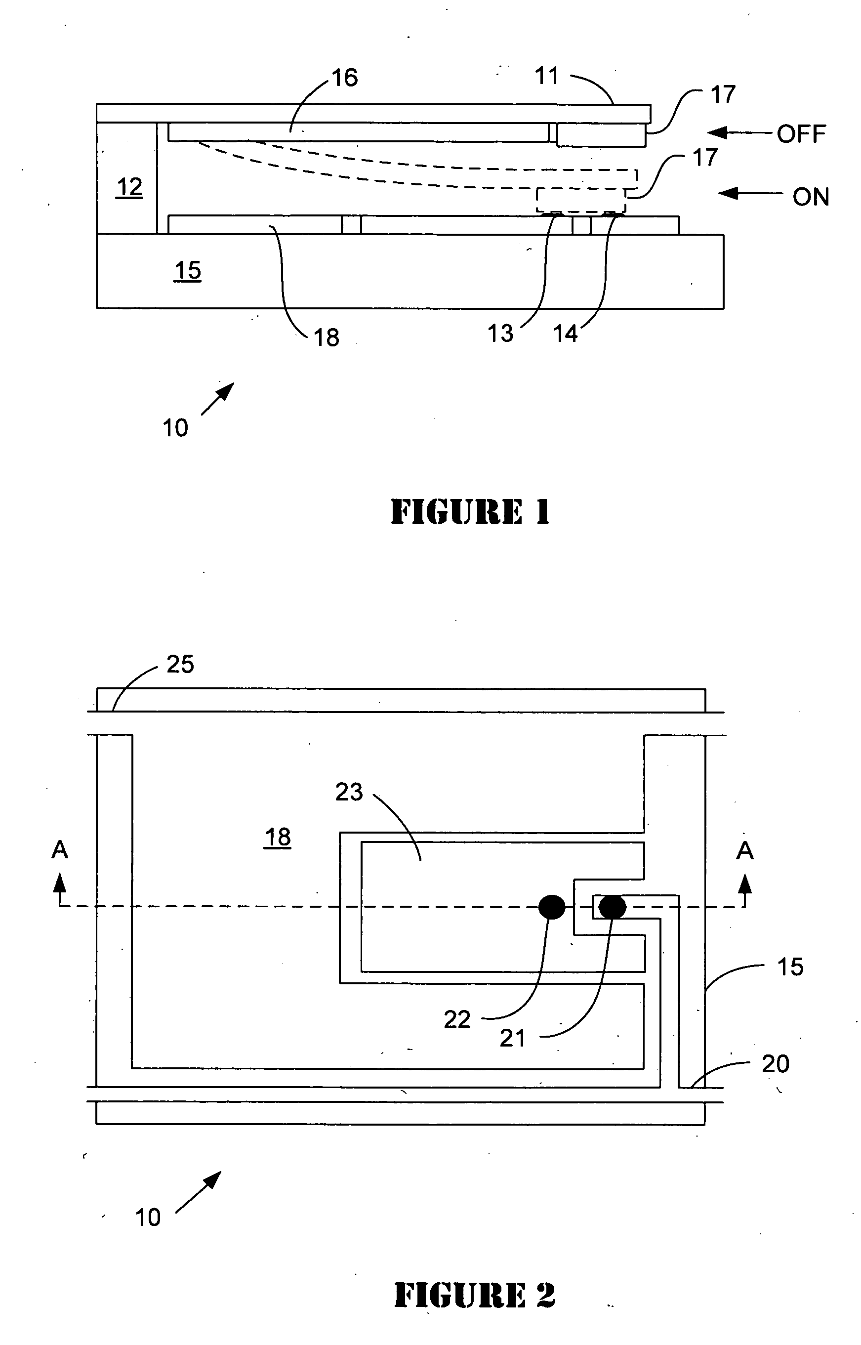
[0013]FIG. 1 is a cross sectional view taken along the line A-A of FIG. 2 and FIG. 3 of an exemplary cell having a cantilevered platform in a micro-electromechanical device in accordance with an embod...
PUM
 Abstract
Description
Claims
Application Information