
Aesthetic dental implant fixture and abutment system

Inactive Publication Date: 2005-11-03
CROHIN CONSTANT C +1
View PDF18 Cites 32 Cited by
  • Summary
  • Abstract
  • Description
  • Claims
  • Application Information

AI Technical Summary

Benefits of technology

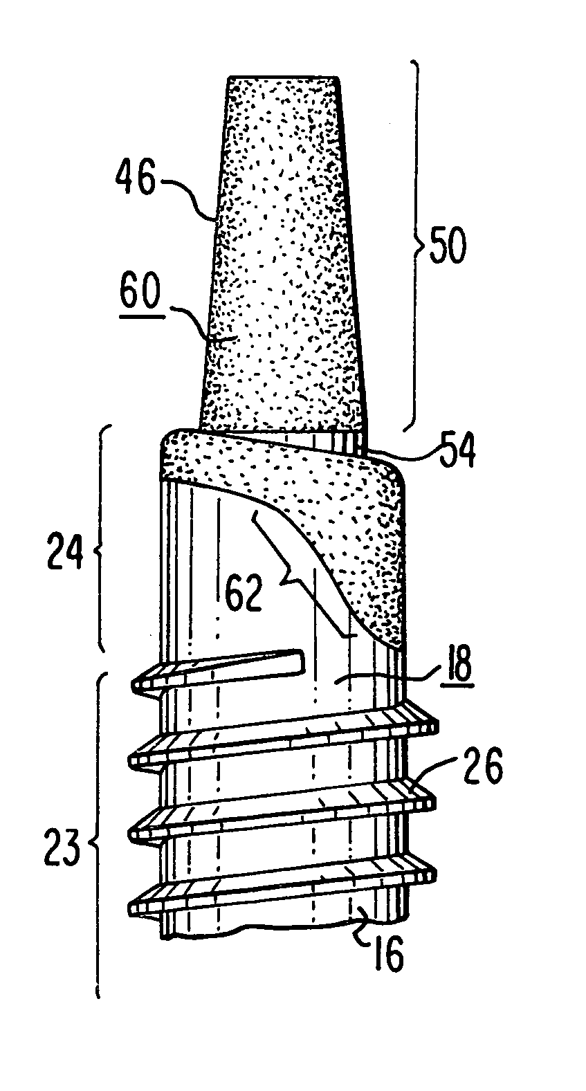
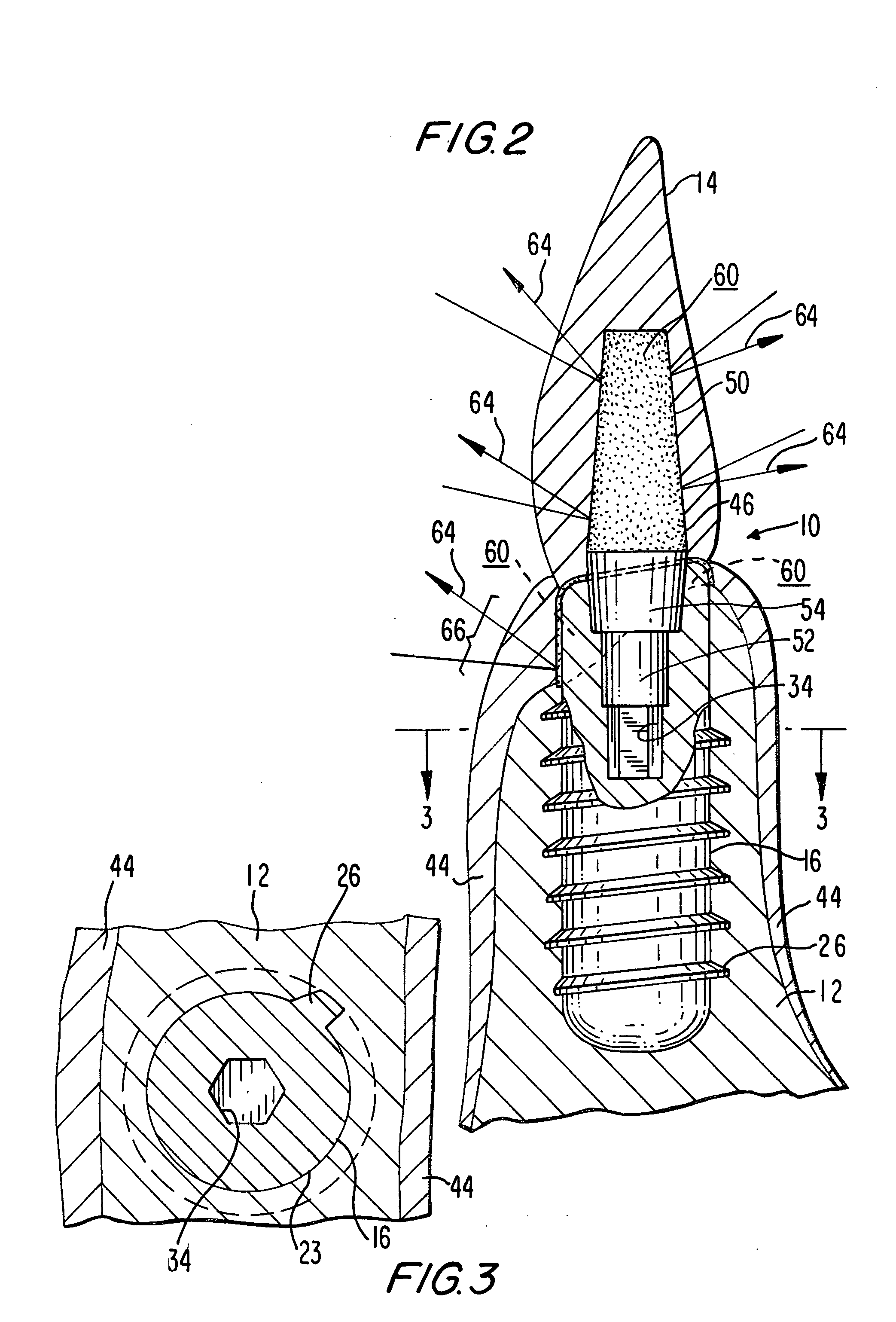
[0010] The objects and advantages of the present invention are achieved by providing a dental implant fixture and abutment system fabricated generally of dental grade titanium alloys, certain portions of which are coated with a bio-compatible material that is capable of camouflaging the unsightly dark and / or shadowy appearance produced by the use of such alloys. The bio-compatible coating material may be applied either to at least a portion of the implant fixture or to at least a portion of the abutment, but preferably it is applied to at least a portion of both of these elements, and most preferably it is applied only to the coronal regions of both of these elements, and is contoured on the implant fixture such that it extends further apically on the facial aspect than on the palatal aspect, allowing for subgingival positioning of the coating on the facial aspect upon placement of the implant. In the preferred embodiments, the bio-compatible coating material comprises gold, which can be applied using a variety of methods, and which provides a highly polished surface that resists plaque adherence and sustains optimal peri-implant health.
[0011] The invention encompasses both one-stage and two-stage dental implants having the foregoing characteristics, and extends to dental restoration systems in which a prosthetic tooth device or crown is combined with a one-stage or two-stage dental implant having such characteristics. Optionally, the implant fixture is shaped such that, upon placement of the implant, the transgingival portions of the implant fixture are more coronal on the palatal aspect and more apical on the facial aspect, accommodating the differences in the residual alveolar ridge morphology and allowing for maintenance of peri-implant bone height post implant placement.

Problems solved by technology

Although the success rate of such implants has been greatly improved in recent years as a result of the use of this material, the increased reliance on such implants especially to replace teeth in the anterior, aesthetically demanding regions of the mouth has increased the challenge to produce a bio-mimetic result.
Unfortunately, the innate chroma of titanium is in the gray-black spectrum which, due to the translucency of the peri-implant structures that surround the implant fixture and abutment, is visible through the prosthesis, and results in the common clinical observation that implants and abutments fabricated of this material yield an unattractive dark root and crown appearance.
Apart from their appearance, current implant / abutment designs also do not satisfactorily accommodate the residual alveolar ridge anatomy that is typical of an edentulous implant site.
In particular, the prior art does not allow for maintenance of the peri-implant bone height, post implant placement, which clinically is typically found to be more coronal on the palatal aspect of the edentulous alveolar ridge, while the facial ridge height is more apical, all of which is due to uneven alveolar bone healing / resorption patterns.
These patterns of bone loss can be influenced by the placement and subsequent loading of an implant in the area, and while some prior art designs do accommodate the alveolar architecture on the facial aspect, they fail to accommodate the more residual ridge anatomy on the palatal aspect, which is more coronal, thus resulting an undesirable loss of peri-implant bone on this aspect of the alveolar ridge.

Method used


Image

  • Aesthetic dental implant fixture and abutment system
  • Aesthetic dental implant fixture and abutment system
  • Aesthetic dental implant fixture and abutment system

Examples


Embodiment Construction

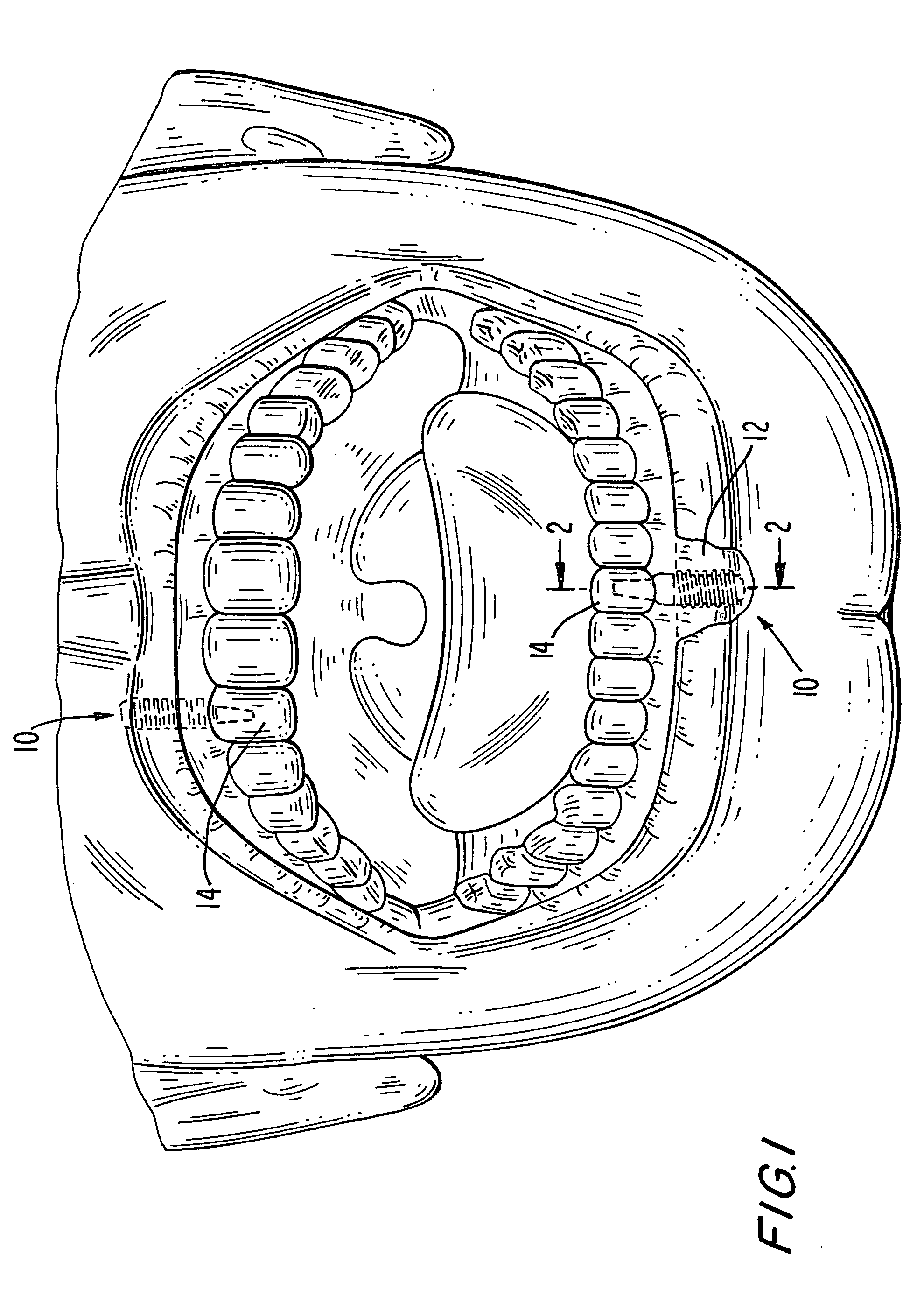
[0022] Referring now to the drawings, FIG. 1 is an illustrative view of an adult human patient's oral cavity or mouth, showing the dentition of both the upper and lower dental arches, and in which an apparatus comprising an aesthetic dental implant fixture and abutment system according to the present invention is generally designated 10. Two instances of apparatus 10 are shown in phantom in FIG. 1, both of which located in the anterior region of the mouth and are already fully inserted into the maxillary bone 12, and both of which are shown already connected to and supporting an associated prosthetic dental restoration (“prosthesis”) 14, shaped and sized to mimic incisor teeth.

[0023] Although the apparatus of the present invention may also be used in the posterior portions of the mouth, in conjunction with a patient's mandibular bone, it will nevertheless be understood by those skilled in the art that the invention will find its primary use in the anterior portions of the mouth, wh...


PUM


Abstract

A dental implant fixture and abutment system for use in restorative dental surgery comprises a thin coating, preferably of gold, applied to certain regions of the implant fixture and to certain regions of the abutment post, so as to mask or camouflage the unattractive dark root and crown appearance of prior art dental restorations which is caused primarily by the innate gray-black chroma of the titanium alloys out of which such restorations are conventionally fabricated. Optionally, the implant fixture may also be shaped such that, upon placement in the mouth, the transgingival portions of the implant fixture are more coronal on the palatal aspect and more apical on the facial aspect, thereby accommodating the differences in the residual alveolar ridge morphology and allowing for maintenance of peri-implant bone height post implant placement. Both one-stage and two-stage dental implant systems having such characteristics are disclosed, as are dental restoration systems in which a prosthetic tooth device or crown is combined with a one-stage or two-stage dental implant having such a characteristics.

Description

REFERENCE TO RELATED APPLICATIONS [0001] This application claims the benefit of prior co-pending U.S. Provisional Patent Application Ser. No. 60 / 566,761, filed Apr. 30, 2004.TECHNICAL FIELD [0002] The present invention relates generally to the field of dental restoration systems, and more specifically to an implant fixture and abutment system that confers an aesthetically pleasing appearance on the entire restoration. BACKGROUND OF THE INVENTION [0003] Dental implants are used in place of missing and / or extracted natural teeth as the base of support for an abutment and a final prosthesis, in an attempt to restore normal oral function and appearance. First, the implant fixture or body is surgically inserted directly into the alveolar bone of a patient's jaw (mandibular or maxillary bone), and once the implant becomes fully integrated with the bone, it is ready to accept an abutment post which is attached using a variety of connection or mating engagement mechanisms of different desig...

Claims


Application Information

Patent Timeline
IPC IPC(8): A61C8/00
CPCA61C8/0012A61C8/0013A61C8/005A61C8/0077A61C8/0059A61C8/006A61C8/0069A61C8/0054
Inventor CROHIN, CONSTANT C.RASOOL, S. FAHEEM
Owner CROHIN CONSTANT C
Learn More