Acoustic lens and ultrasonic probe using the lens

a technology of ultrasonic probe and lens, which is applied in the field of acoustic lens and ultrasonic probe using the lens, can solve the problems of desensitizing the ultrasonic probe as a whole, and increasing the ultrasonic propagation loss, so as to increase the sensitivity of the ultrasonic probe, and reduce the loss of ultrasonic propagation. small

Inactive Publication Date: 2005-11-03
NIHON DEMPA KOGYO CO LTD
View PDF8 Cites 13 Cited by
  • Summary
  • Abstract
  • Description
  • Claims
  • Application Information

AI Technical Summary

Benefits of technology

[0012] According to such a structure, if the acoustic lens of the present invention is applied to an ultrasonic probe, since the ultrasonic propagation loss in the leg portion of the acoustic lens can be minimized, there is the effect of increasing the sensitivity of the ultrasonic probe as a whole.
[0013] Moreover, in the present invention, the leg portion of the acoustic lens is formed with opposite end sides thereof in a bent L-shape. Accordingly, it becomes suitable as an acoustic lens for an ultrasonic probe.
[0014] Furthermore, in the present invention, an ultrasonic probe is constructed by adhering onto a piezoelectric element group where a plurality of piezoelectric elements are arranged side by side, an acoustic lens comprising the lens portion having curvature in the lengthwise direction of the piezoelectric elements. Accordingly, an ultrasonic probe having little ultrasonic propagation loss and high sensitivity can be obtained.
[0015] Moreover, in another embodiment of the present invention, since the piezoelectric elements and the lens portion have the same length, the ultrasonic propagation loss can be further decreased by minimizing the thickness of the lens portion.

Problems solved by technology

However, such a conventional ultrasonic probe has a problem of desensitization caused by the acoustic lens 40.
Therefore, due to such a structure, there is a problem of desensitization of the ultrasonic probe as a whole, by increasing the ultrasonic propagation loss due to the acoustic lens 40 over and above what is necessary.

Method used


Image

  • Acoustic lens and ultrasonic probe using the lens
  • Acoustic lens and ultrasonic probe using the lens
  • Acoustic lens and ultrasonic probe using the lens

Examples


embodiment

[Embodiment]

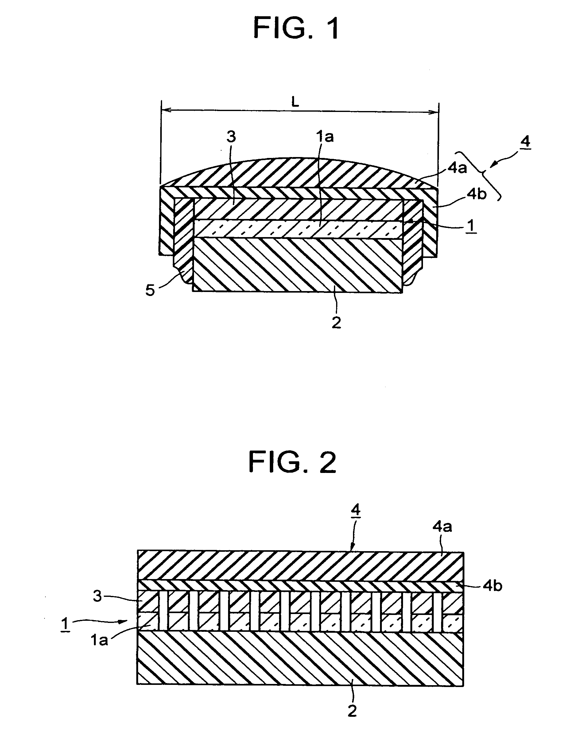
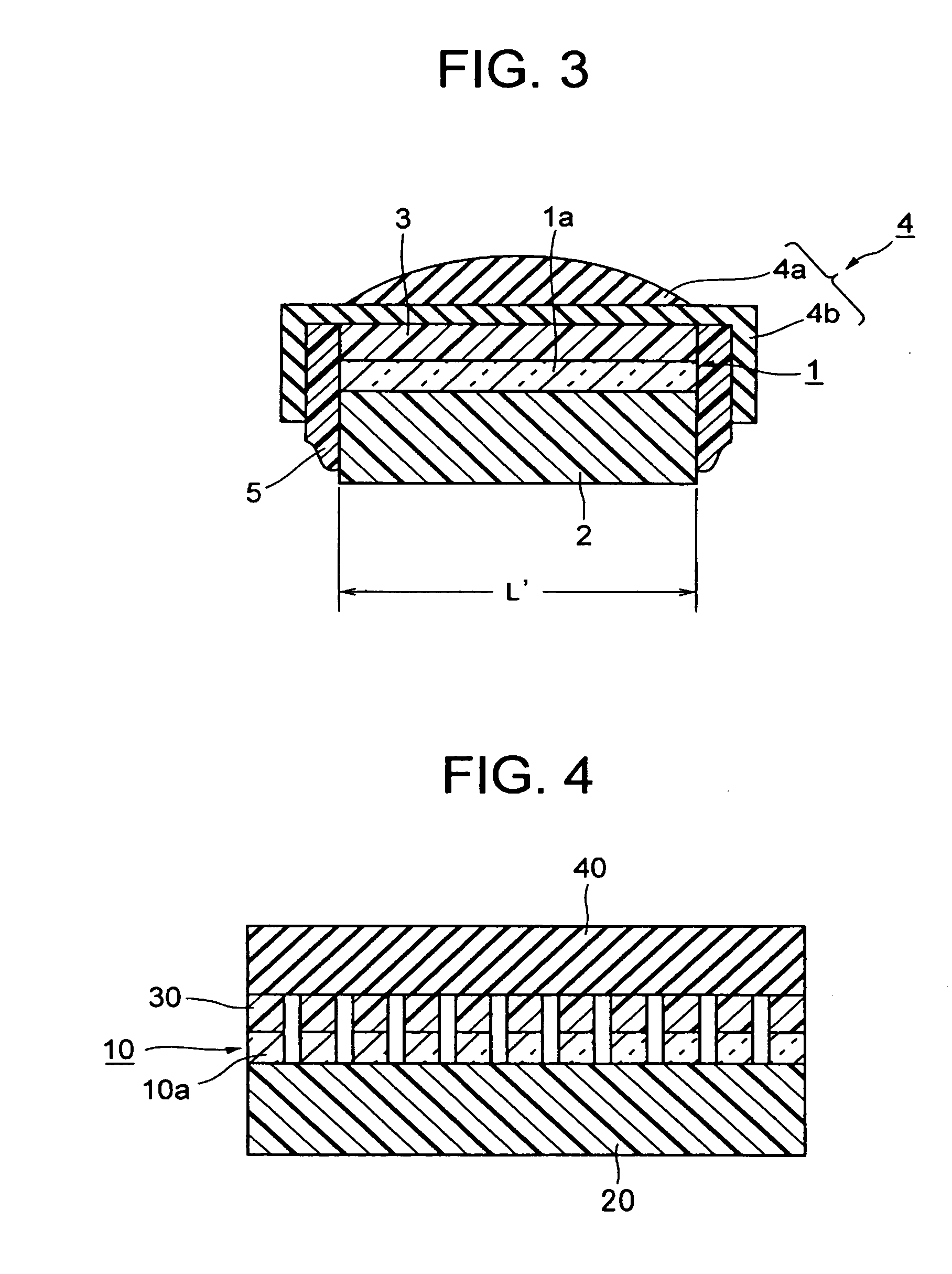
[0021]FIG. 1 is a longitudinal (lengthwise direction) cross-sectional view explaining an embodiment of an ultrasonic probe of the present invention.

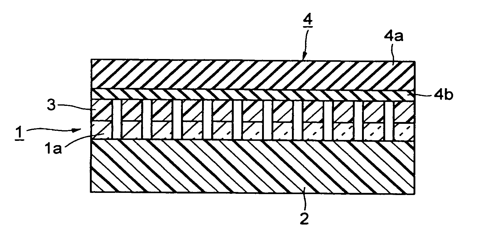
[0022]FIG. 2 is a transverse (widthwise direction) cross-sectional view of the ultrasonic probe shown in FIG. 1.

[0023] As shown in FIG. 1 and FIG. 2, the ultrasonic probe of the present invention is constructed by adhering onto a piezoelectric element group 1 which is firmly adhered onto a backing material 2 and has an acoustic matching layer 3 on the front face, an acoustic lens 4 comprising a lens portion 4a having curvature formed in the lengthwise direction of the piezoelectric element 1a, and bent L-shape leg portions connected by a planar portions 4b.

[0024] In this embodiment, the lens portion 4a of the acoustic lens 4 is formed from silicone rubber, and the leg portion 4b is formed from polyimide resin having good attenuation prevention properties. These are formed by adhering the lens portion 4a which is made from ...


PUM

PropertyMeasurementUnit
ultrasonic propagation lossaaaaaaaaaa
L-shapeaaaaaaaaaa
ultrasonic probeaaaaaaaaaa

Abstract

The invention has a structure, in an acoustic lens for an ultrasonic probe comprising leg portions which are connected by a planar shape, and a lens portion which is provided on the leg portions and has curvature in the lengthwise direction, wherein the leg portions are made from an attenuation prevention material having the less ultrasonic propagation loss than for the lens portion. Moreover, the leg portions of the acoustic lens are formed with opposite end sides thereof in a bent L-shape. Furthermore, an ultrasonic probe is constructed by adhering onto a piezoelectric element group where a plurality of piezoelectric elements are arranged side by side, an acoustic lens provided with curvature in the lengthwise direction.

Description

BACKGROUND OF THE INVENTION [0001] The present invention relates to an acoustic lens and an ultrasonic probe using the lens, and in particular relates to an acoustic lens in which the ultrasonic propagation loss is minimized. [0002] An ultrasonic probe is used as an ultrasonic echo sounder transducer, for example in medical ultrasonic diagnostic equipment. As one such ultrasonic probe, there is one where piezoelectric elements are arranged in the widthwise direction of the ultrasonic probe and electronic scanned, and further an acoustic lens having curvature in the lengthwise direction is adhered thereto so as to improve the resolution. [0003]FIG. 4 is a transverse cross-sectional view of a conventional example of an ultrasonic probe described below, while FIG. 5 is a longitudinal cross-sectional view thereof. [0004] As shown in FIG. 4 and FIG. 5, the conventional ultrasonic probe comprises; a piezoelectric element group 10, a backing material 20, an acoustic matching layer 30, and ...

Claims


Application Information

Patent Timeline
Patent Type & Authority Applications(United States)
IPC IPC(8): A61B8/00G01N29/24A61B8/14G10K11/30
CPCG10K11/30
Inventor WAKABAYASHI, TAKASHI
Owner NIHON DEMPA KOGYO CO LTD
Why Eureka
Try Eureka