Delivery system for vascular prostheses and methods of use

a delivery system and prosthesis technology, applied in the field of two-part delivery system, can solve the problems of limited ability to reduce the overall profile of the delivery system, limited ability to access smaller vessels, and small overall reduction of the delivery profile, so as to achieve the effect of reducing the profil

Inactive Publication Date: 2005-11-03
NOVOSTENT CORP
View PDF22 Cites 97 Cited by
  • Summary
  • Abstract
  • Description
  • Claims
  • Application Information

AI Technical Summary

Benefits of technology

[0015] In view of the foregoing, it is an object of the present invention to provide a delivery system and methods that provide a reduced profile, thereby enabling the delivery system to negotiate small diameter vessels.
[0016] It is another object of this invention to provide a delivery system and methods that provide low rigidity in the delivery configuration, thereby allowing the delivery system to negotiate highly tortuous anatomy.
[0017] It is a further object of the present invention to provide a stent delivery system for self-expanding stents and methods of use that provide a desired degree of foreshortening (including zero foreshortening) of the stent during deployment.
[0019] In one preferred embodiment, the sheath is constructed of a thin-walled material with a non-stick interior liner, e.g., such as polytetrafluoroethylene, and has the same inner diameter as the inner diameter of the loader tube. This permits that loader tube to be coupled to the sheath so that the stent may be transferred from the loader tube to the sheath while the stent is retained in the contracted delivery configuration. Because the stent is not stored in the sheath, as in previously known systems, but only passes in a transitory manner through the sheath during delivery, the wall thickness of the sheath may be substantially thinner than in previously known delivery systems and substantially more flexible.
[0021] The foregoing method of the present invention thus permits the sheath to be separately advanced through highly tortuous anatomy. Because the sheath does not contain the stent when originally advanced through the patient's vessel, it is much less rigid than previously-known delivery systems. In addition, once the distal end of the sheath is inserted to a desired location within a vessel, the loader tube permits the stent to be pushed into and through the sheath in the contracted state. This feature ensures that there is no increase in the profile of the delivery system, and permits stents of the present invention to be delivered using sheaths as small as 3 French.

Problems solved by technology

Conventional stent delivery systems have problems negotiating vessels having reduced diameters and vessels that require tortuous or challenging anatomy to be traversed.
While such previously-known systems eliminated the sheath of the delivery system, the use of locking mechanisms required that the diameter of the catheter increase, so that little overall reduction in delivery profile was accomplished.
Likewise for balloon expandable stent delivery systems, the ability to reduce the overall profile of the delivery system was limited by of thickness of the stent compressed onto the deflated balloon, the balloon inflation lumen diameter and guide wire lumen diameter, and need to make the inflation lumen walls sufficiently thick to withstand the inflation pressures required to deploy the stent.
This in turn has limited the ability to access smaller vessels and negotiate highly tortuous anatomy.
In addition to the foregoing drawbacks of previously-known stent delivery systems, the acceptance of self-expanding stents has been limited by problems peculiar to the design of such stents.
Specifically, self-expanding stents may experience large length changes during expansion (referred to as “foreshortening”) and may shift within the vessel prior to engaging the vessel wall, resulting in improper placement.
U.S. Pat. No. 4,768,507 to Fischell et al. and U.S. Pat. No. 6,576,006 to Limon et al., each describe the use of a groove disposed on an inner member of the delivery system to prevent such axial movement, but such arrangements detrimentally increase the profile of the delivery system.
Moreover, those delivery systems do not address the issue of stent foreshortening.

Method used


Image

  • Delivery system for vascular prostheses and methods of use
  • Delivery system for vascular prostheses and methods of use
  • Delivery system for vascular prostheses and methods of use

Examples


Embodiment Construction

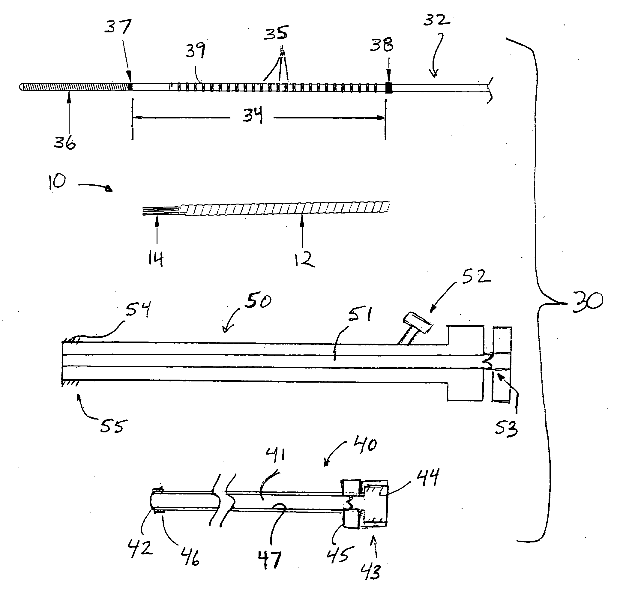
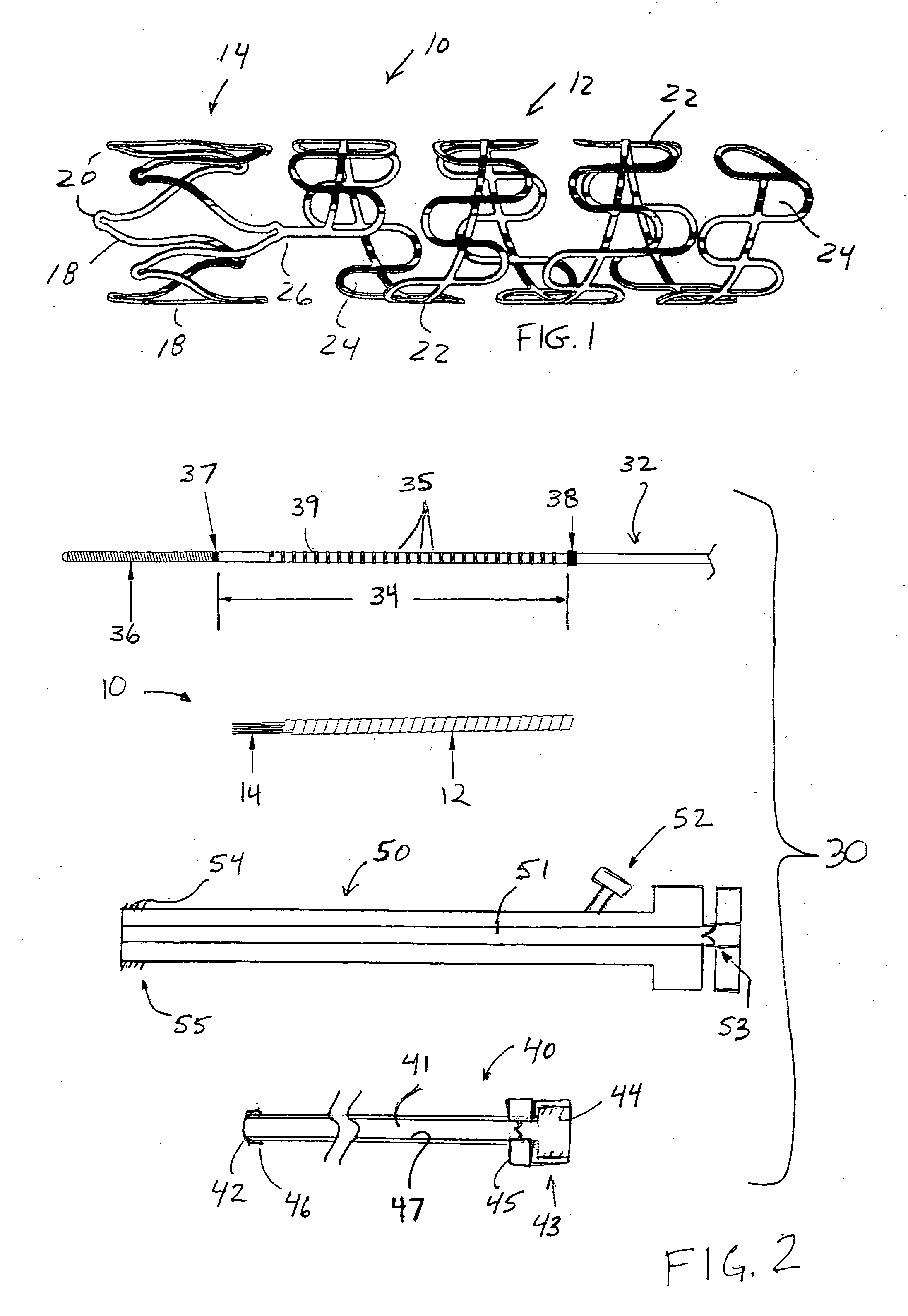
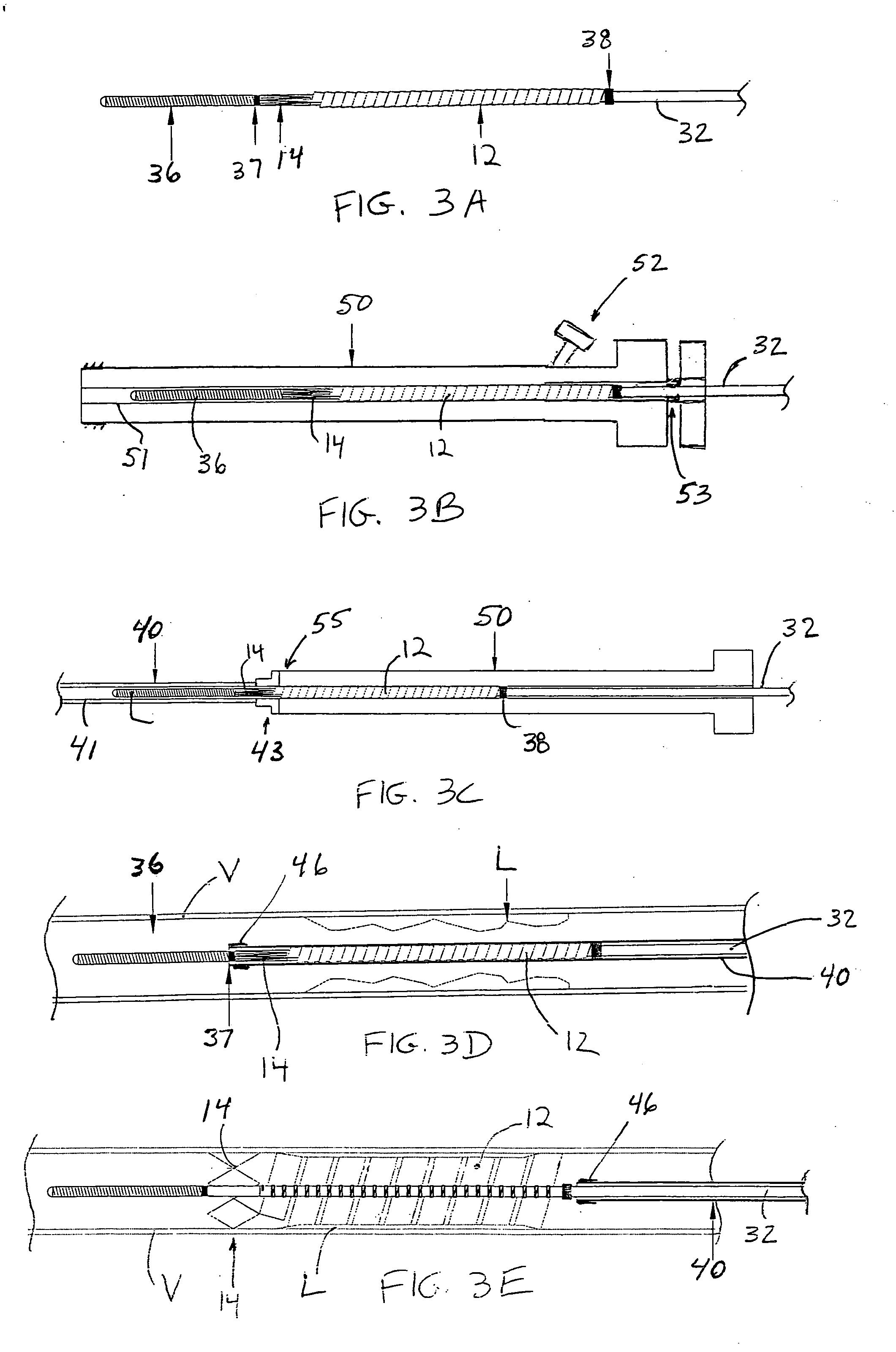
[0030] The present invention is directed to a delivery system for use with implantable vascular prostheses for a wide range of applications, such as treating aneurysms, maintaining patency in a vessel, and allowing for the controlled delivery of therapeutic agents to a vessel wall. In a preferred embodiment, the delivery system is configured for use with a stent having a helical ribbon portion joined, at its distal end, to a radially self-expanding anchor portion, such as depicted in FIG. 1.

[0031] Referring to FIG. 1, an exemplary stent for use with the delivery system of the present invention is described. As used in this specification, the terms “vascular prosthesis” and “stent” are used interchangeably. Vascular prosthesis 10 comprises helical section 12 and distal section 14, each capable of assuming contracted and deployed states. In FIG. 1, helical section 12 and distal section 14 are each depicted in the deployed state.

[0032] Vascular prosthesis 10 preferably is formed from...


PUM


Abstract

The present invention is directed to a delivery system for delivering a vascular prosthesis within a vessel, the vascular prosthesis having a contracted delivery configuration and a deployed configuration. The delivery system comprises a loader tube having a lumen preloaded with a delivery wire carrying a vascular prosthesis in the contracted delivery configuration. A separately inserted sheath includes a lumen configured to accept the vascular prosthesis, while retaining it in the contracted delivery configuration. The delivery wire is used to translate the vascular prosthesis to a distal end of the sheath for deployment in a vessel.

Description

REFERENCE TO RELATED APPLICATIONS [0001] The present application is a continuation-in-part application of co-pending, commonly assigned U.S. patent application Ser. No. 10 / 836,909, filed Apr. 30, 2004.FIELD OF THE INVENTION [0002] The present invention relates to a two-part delivery system for implantable vascular prostheses, wherein the delivery system provides reduced profile and enhanced flexibility to negotiate narrow vessels and tortuous anatomy. BACKGROUND OF THE INVENTION [0003] Vascular stenting has become a practical method of reestablishing blood flow to diseased vasculature. Conventional stent delivery systems have problems negotiating vessels having reduced diameters and vessels that require tortuous or challenging anatomy to be traversed. Today there are a wide range of intravascular prostheses on the market for use in the treatment of aneurysms, stenosis, and other vascular irregularities. Balloon expandable and self-expanding stents are well known for restoring patenc...

Claims


Application Information

Patent Timeline
Patent Type & Authority Applications(United States)
IPC IPC(8): A61F2/06A61F2/84A61F2/88A61F2/90
CPCA61F2/88A61F2/966A61F2/95A61F2/91
Inventor HOGENDIJK, MICHAELLEOPOLD, ERICHUYNH, TIMALEXANDER, MILES
Owner NOVOSTENT CORP
Why Eureka
Try Eureka