Door closer

a door closer and air tightness technology, applied in the field of door closers, can solve the problems of poor buffering effect, high production cost of this kind of door closer, and easy leakage of oil, so as to improve the air tightness of the door closer, reduce the hydraulic oil volume, and prolong the service life

Inactive Publication Date: 2005-11-10
HUANG TAN CHENG
View PDF11 Cites 16 Cited by
  • Summary
  • Abstract
  • Description
  • Claims
  • Application Information

AI Technical Summary

Benefits of technology

[0011] The primary object of the present invention is to seal the hydraulic oil in the inner pipe of the sliding cylinder and the oil-replenishing cylinder, so in the housing of the door closer is not filled with hydraulic oil. Moreover, only at side of the sliding cylinder and oil-replenishing cylinder is provided with sealing device. In this case, the present invention is able to reduce the hydraulic oil volume and improve the air-tightness of the door closer.
[0012] Another object of the present invention is to provide a door closer that has longer service life. The sliding cylinder is interiorly formed with inner pipe, the oil replenishing cylinder and piston shaft. Since the sliding cylinder is formed with teeth on the outer surface thereof for driving purpose, the siding cylinder must be made of high-strength and high density steel material. In this case, the fit tolerance of hole and shaft is very small when the inner pipe of t

Problems solved by technology

This kind of hydraulic (pneumatic) door closer has been commonly applied to all kinds of doors and windows, however, there are still some disadvantages will be resulted from real operation as follows:
Thereby, the production cost of this door closer is pretty high.
Moreover, the problem of gas cavity is difficult to be eliminated completely, so the door closer of this kind is susceptible to oil-leak.
Second, the hydraulic oil used in the conventional door closer must be easy to flow, so the tolerance of fit between the piston and the oil cylinder must be very small, so as to prevent the hydraulic oil leaking from the clearance between the piston and the oil cylinder and result in a bad buffering effect.
Since

Method used


Image

  • Door closer
  • Door closer
  • Door closer

Examples


first embodiment

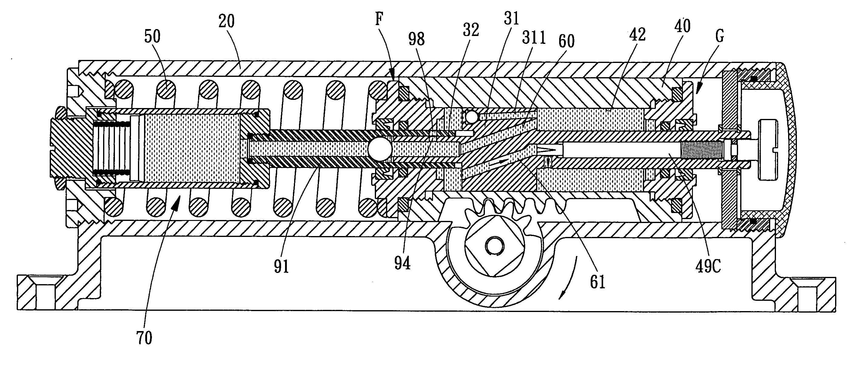
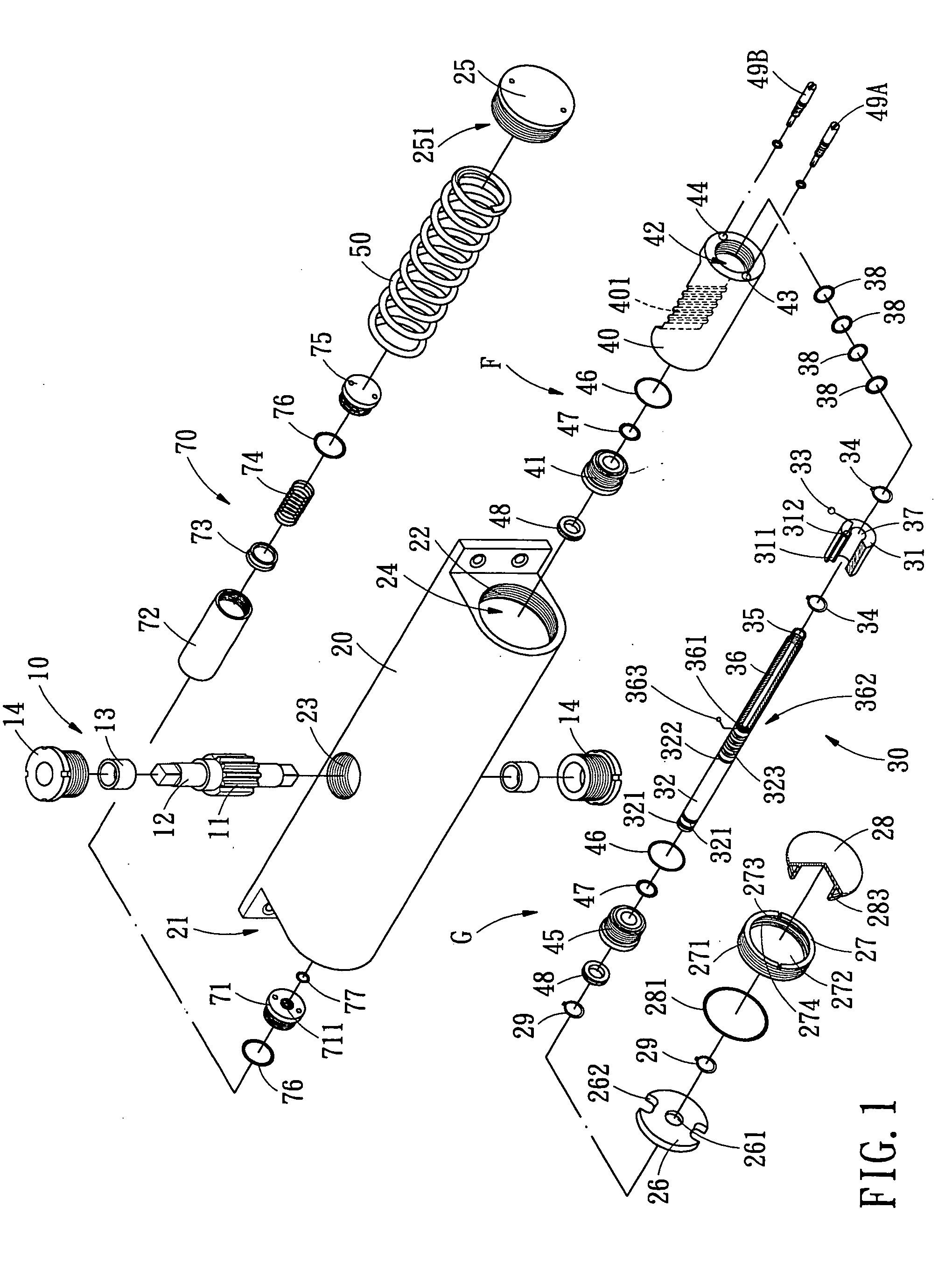
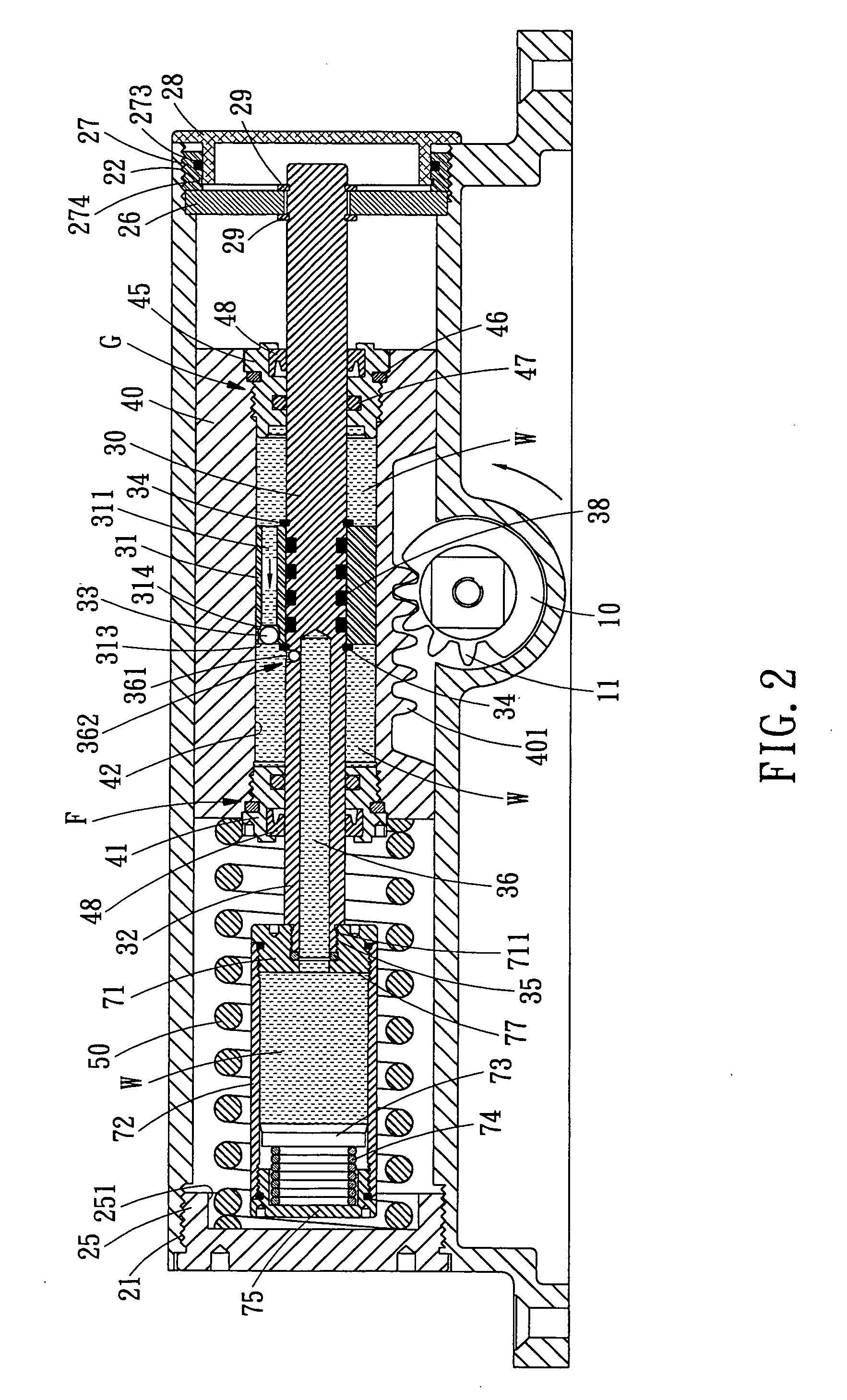
[0051] Referring to FIGS. 2-10, which shows the door closer in accordance with the present invention, wherein:

[0052] As shown in FIGS. 2 and 3, when the user opens the door by force, the panel of the door drives the gear wheel 11 of the door shaft 10 to rotate counterclockwise, and the gear wheel 11 will move the sliding cylinder 40 toward the door-closing spring 50 by driving the teeth 401. In this case, the door-closing spring 50 is compressed by the cylinder 40. Since the piston shaft 30 is fixed to the positioning member 62 of the housing 20 by virtue of the two C-shaped rings 29, both the leak-proof assemblies F and G at both sides of the sliding cylinder 40 are slidably mounted on the shaft 32 of the piston shaft 30 in a hermetic manner by cooperating with the sliding bushes 41, 45, the outer seal rings 46, the inner seal rings 47 and the oil-sealing members 48, the hydraulic oil W will be compressed by the piston 31 and the sliding bush 45, such that the pressure of the hydra...

third embodiment

[0058] Referring further to FIG. 13, which shows a piston shaft 30 in accordance with the present invention, wherein the shaft 32 and the piston 31 can be integrally formed.

fourth embodiment

[0059] Referring to FIGS. 14a, 14b and 14c, which show a fourth embodiment in accordance with the present invention, the piston 31 of the the piston shaft 30 can be provided on an outer periphery thereof with wearable ring 87, both ends at junction of the wearable ring 87 are step-configured and connected to each other in a stepped manner, so as to prevent leakage of the hydraulic oil W from this junction.


PUM


Abstract

The present invention relates to a door closer, in a housing of which is received a sliding cylinder, the sliding cylinder is provided with teeth on an outer periphery thereof for meshing with a gear wheel of a door shaft, a sliding cylinder interiorly formed with inner pipe serves to move relative to a piston of a piston shaft. At an end of the piston shaft is provided with an oil-replenishing cylinder that serves to replenish hydraulic oil to the sliding cylinder via a one-way valve.

Description

BACKGROUND OF THE INVENTION [0001] 1. Field of the Invention [0002] The present invention relates to a door closer, and more particularly to an auxiliary buffering structure which is used on doors and / or windows. [0003] 2. Description of the Prior Arts [0004] The conventional door closers sold in market usually have a cylinder filled with hydraulic oil that is used as an operating space for other components. The hydraulic (pneumatic) door closer is disposed between the door and a wall to provide buffering effect at the end of a door opening or closing action. This kind of hydraulic (pneumatic) door closer has been commonly applied to all kinds of doors and windows, however, there are still some disadvantages will be resulted from real operation as follows: [0005] First, the cylinder of the conventional door closer is filled with hydraulic oil and formed by aluminous die-casting. To avoid oil leak caused by gas cavities, the producer has to filter the aluminous liquid for several tim...

Claims


Application Information

Patent Timeline
IPC IPC(8): E05F1/08E05F3/10E05F3/12
CPCE05F3/102E05F3/12E05Y2201/458E05Y2201/20E05Y2201/234Y10T16/293E05Y2900/132Y10T16/2804Y10T16/2766Y10T16/577E05Y2201/254
Inventor HUANG, TAN-CHENG
Owner HUANG TAN CHENG
Why Eureka
Try Eureka