
Polymeric foam scrim sheathings

Inactive Publication Date: 2005-11-10
PACTIV CORP
View PDF53 Cites 3 Cited by
  • Summary
  • Abstract
  • Description
  • Claims
  • Application Information

AI Technical Summary

Benefits of technology

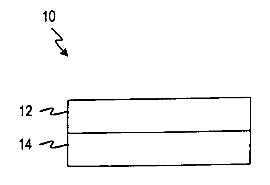
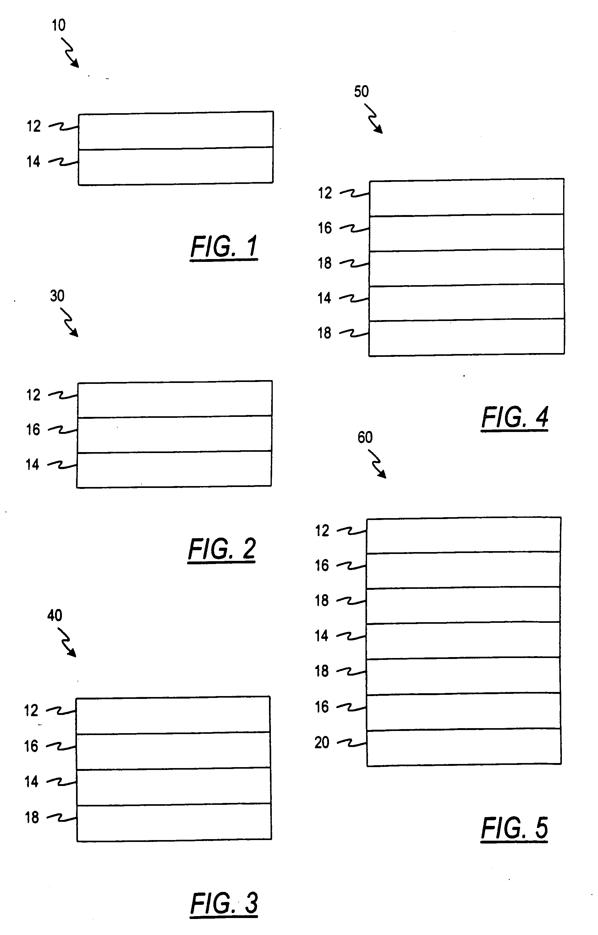
[0006] According to one embodiment of the present invention, a sheathing adapted to be fastened to at least one wall supporting structure comprises at least two layers. The first layer comprises a polymeric foam layer. The second layer comprises a polymeric scrim, and is located adjacent to the first layer. The second layer has means for reinforcing its periphery so as to inhibit failure of the sheathing. The reinforcing means may include a selvage tuck or a folded-over edge.
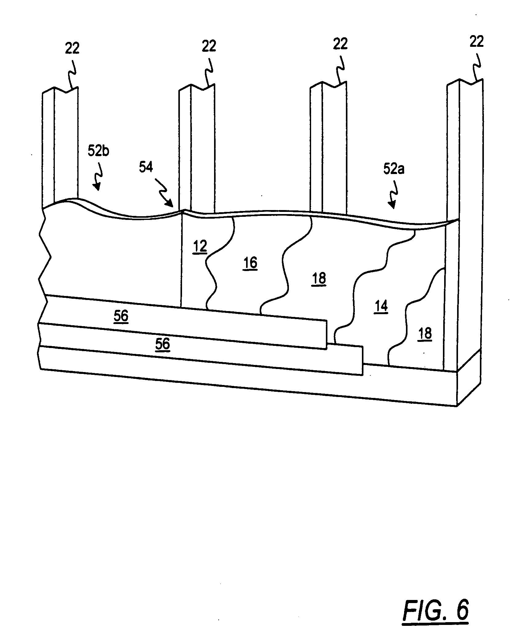
[0007] According to another embodiment of the present invention, a sheathing adapted to be fastened to at least one wall supporting structure comprises at least three layers. The first layer comprises a polymeric foam layer, while the second layer comprises a polymeric cross-woven scrim. The second layer has means for reinforcing its periphery so as to inhibit failure of the sheathing. The third layer comprises an impact polystyrene and is located between the first and the second layers.
[0008] According to one method of the present invention, a sheathing is provided that comprises at least two layers. The first layer comprises a polymeric foam layer. The second layer comprises a polymeric scrim and is located adjacent to the first layer. The second layer has means for reinforcing its periphery so as to inhibit failure of the sheathing. The sheathing is installed to a wall supporting structure.

Problems solved by technology

These products, however, have disadvantages such as being heavy and difficult to install, providing little insulation and / or having poor moisture resistance.
These existing foamed materials, however, have disadvantages such as their lack of strength as measured by wind resistance.
This is shown, for example, by their failures to withstand 100 miles per hour winds when installed behind exterior facing such as siding or brick.
Wind resistance may cause problems such as fracturing, cracking and / or edge pull out of the sheathing from the fasteners.
Existing foam sheathing is still susceptible to damage at the building site prior to installation.
This problem is further evident when, for example, delays occur in the installation and / or the installation occurs in extreme weather conditions.
One common example of damage that may occur is when a piece breaks off from a remainder of the sheathing during the process of installation or by vandalism after installation at the building site before being covered with an exterior facing such as siding, brick, or stucco.

Method used


Image

  • Polymeric foam scrim sheathings
  • Polymeric foam scrim sheathings
  • Polymeric foam scrim sheathings

Examples


example 1

[0059] Negative wind pressure load tests were conducted on samples of sheathing (“Sheathing 1”) using a 2×4 (1½ inches×3½ inches) stud as a wall supporting structure. Sheathing 1 had dimensions of 48 inches by 90 inches (48″×90″). Sheathing 1 consisted of five layers with the first layer being a woven polypropylene scrim with a selvage tack. The second layer was made of a BYNEL® adhesive. The third and fifth layers were made of high impact polystyrene. The second layer was located between the first and third layers. The fourth layer was a polystyrene foam and was located between the third and fifth layers. This is a similar structure as shown above in FIG. 4. The following describes the test specimens that were used in Example 1.

[0060] Example 1 Specimen Description

[0061] A. Materials [0062] 1. Stud: 2×4, Stud Grade spruce pine fur (SPF) spaced at 16″ on center (o.c.) [0063] 2. Top Plate: Single 1×4, Ungraded SPF [0064] 3. Bottom Plate: Single 1×4, Ungraded SPF [0065] 4. Gypsum: 5...

example 2

[0084] Negative wind pressure load tests were conducted on samples of 48″×90″ Sheathing 1 (described above in Example 1) without a selvage tuck on the scrim layer using a 2×4 stud as a wall supporting structure. The following describes the test specimens that were used in Example 2.

[0085] Example 2 Specimen Description

[0086] A. Materials [0087] 1. Stud: 2×4, Stud Grade SPF spaced at 16″ (o.c.) [0088] 2. Top Plate: Single 1×4, Ungraded SPF [0089] 3. Bottom Plate: Single 1×4, Ungraded SPF [0090] 4. Gypsum: 5 / 16″ U.S. Gypsum [0091] 5. Siding: Georgia Pacific Parkside® D5 Vinyl Siding with a nailing flange thickness of 0.038 inch.

[0092] B. Fastening [0093] Top plate attached to studs with five (5)— 7 / 16″×1¾″×16 Ga. Staples. [0094] Bottom plate attached to studs with five (5)— 7 / 16″×1¾″×16 Ga. Staples. [0095] Sheathing 1 fastened with 1″×1½″×16 Ga. staples at 3″ o.c. around perimeter and 3″ o.c. in the field. [0096] Gypsum glued to frame with a ⅜″ bead of PVA glue on all framing membe...

example 3

[0105] Negative wind pressure load tests were conducted on samples of 48″×90″ Sheathing 1 (described above in Example 1) without a selvage tuck on the scrim layer using a 2×6 stud as a wall supporting structure. The following describes the test specimens that were used in Example 3.

[0106] Example 3 Test Specimen Description

[0107] A. Materials [0108] 1. Wall Stud: 2×6, Stud Grade SPF spaced at 16″ (o.c.) [0109] 2. Top Plate: Single 1×6, Ungraded SPF [0110] 3. Bottom Plate: Single 1×6, Ungraded SPF [0111] 4. Siding: Georgia Pacific Parkside® D5 Vinyl Siding with a nailing flange thickness of 0.038 inch.

[0112] B. Fastening [0113] Top plate attached to studs with five (5)— 7 / 16″×1¾″×16 Ga. Staples. [0114] Bottom plate attached to studs with five (5)— 7 / 16″×1¾″×16 Ga. Staples. [0115] Adhesive—Not used [0116] Gypsum—Not used [0117] Sheathing 1 fastened with 1″×1¼″×16 Ga. Staples, Angled at 45 degrees at 3″ o.c. in the field and 3″ o.c. around perimeter. [0118] Siding fastened to sheath...


PUM

PropertyMeasurementUnit
Lengthaaaaaaaaaa
Thicknessaaaaaaaaaa
Thicknessaaaaaaaaaa

Abstract

A sheathing adapted to be fastened to at least one wall supporting structure comprises at least two layers. The first layer comprises a polymeric foam layer. The second layer comprises a polymeric scrim and is located adjacent to the first layer. The second layer reinforces its periphery so as to inhibit the failure of the scrim. The reinforced periphery may include a selvage tuck or a folded-edge.

Description

FIELD OF THE INVENTION [0001] The present invention relates generally to sheathings that are used in structures and, more particularly, to polymeric foam sheathing materials that are used in prefabricated housing and site built housing. BACKGROUND OF THE INVENTION [0002] There are different commercial sheathings that are used in the construction of buildings. Sheathings include materials that span the frame supports of buildings. Some of the commercial products that have been used as sheathing include thin composite laminations, fiberboard, orientated strand board (OSB) and plywood. Some of these products provide structural strength, durability and / or rigidity. These products, however, have disadvantages such as being heavy and difficult to install, providing little insulation and / or having poor moisture resistance. [0003] There are other commercial products that are available as sheathing. For example, polyisocyanurate foam, extruded polystyrene foam, and molded expanded polystyren...

Claims


Application Information

Patent Timeline
IPC IPC(8): B32B3/24B32B5/18B32B5/24B32B7/12B32B27/28D04H13/00E04B1/80E04B2/70E04C2/34E04F13/08
CPCB32B3/266B32B5/18B32B5/24B32B7/12E04F13/0864D04H13/002E04B1/80E04B2/706B32B27/28Y10T428/249953Y10T428/249985B32B27/12B32B27/08B32B5/245B32B27/32B32B5/024B32B2419/00
Inventor NORDGREN, DOUGLAS S.LUBKER, JOHN W. II
Owner PACTIV CORP
Learn More