
Power supply for measuring the line impedance of underground cable

a technology of power supply and underground cable, which is applied in the direction of electric variable regulation, process and machine control, instruments, etc., can solve the problems of large errors in measured impedance values, difficulty in boosting power, and cut in power of underground cable lines or breakage of impedance measurement equipment, etc., to achieve the effect of removing nois

Inactive Publication Date: 2005-11-10
LG CABLE LTD (KR)
View PDF6 Cites 4 Cited by
  • Summary
  • Abstract
  • Description
  • Claims
  • Application Information

AI Technical Summary

Benefits of technology

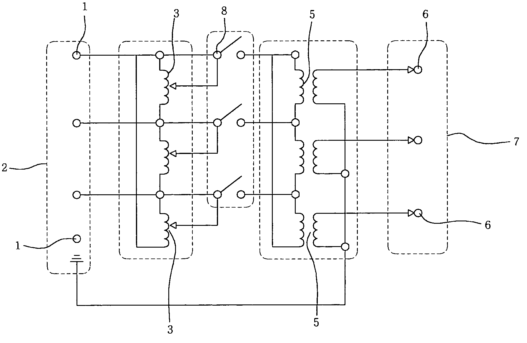
[0006] Therefore, the present invention has been made in view of the above problems, and it is an object of the present invention to provide a power supply for measuring the line impedance of an underground cable, wherein a plurality of autotransformers are simultaneously controlled by a transformer adjustment tap to boost the power supplied respectively to the autotransformers at the same transformation rate, and the 3rd-harmonics of the powers are cancelled in a 3rd-harmonics cancellation transformer to remove noise, whereby the powers boosted at the same transformation rate are applied in a stable manner to the phases of the underground cable, respectively.

Problems solved by technology

This conventional impedance measurement method has the following problems.
First, it is very difficult to boost the power, which is applied respectively to the phases of an underground cable conductor, at the same transformation rate.
In addition, since the measurement is affected by the third harmonics, large errors occur in the measured impedance values.
Further, there are risks that an abrupt voltage variance may cause a cut in power of the underground cable line or breakage of impedance measurement equipment.

Method used


Image

  • Power supply for measuring the line impedance of underground cable
  • Power supply for measuring the line impedance of underground cable
  • Power supply for measuring the line impedance of underground cable

Examples


Embodiment Construction

[0011] Now, a preferred embodiment of the present invention will be described in detail with reference to the drawings.

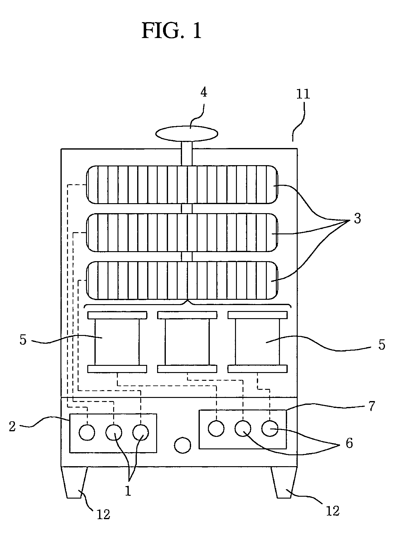
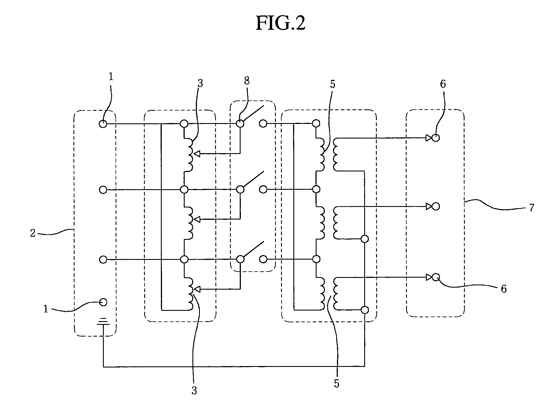
[0012] As shown in FIGS. 1 and 2, in order to measure the impedance of a three-phase underground cable, an input terminal section 2 composed of three input terminals 1 is formed on a body 11 of a specific size at a lower portion thereof. Each input terminal 1 of the input terminal section 2 is individually connected to the utility power, so that powers to be used to measure the underground cable impedance are inputted to the input terminals 1, respectively.

[0013] Three autotransformers 3 connected respectively to the input terminals 1 of the input terminal section 2 are formed vertically in parallel inside the body 11 at an upper portion. A transformer adjustment tap 4, connected to all three of the autotransformers 3, is formed on the body 11 at an upper portion thereof. The transformer adjustment tap 4 simultaneously controls the autotransformers 3 to equally tr...


PUM

PropertyMeasurementUnit
impedanceaaaaaaaaaa
voltageaaaaaaaaaa
currentaaaaaaaaaa

Abstract

Disclosed is a power supply for measuring the line impedance of an underground cable, which includes an input terminal section having a plurality of input terminals, a plurality of autotransformers, a transformer adjustment tap, a plurality of 3rd-harmonics cancellation transformers, and an output terminal section having a plurality of output terminals. The autotransformers are connected respectively to the input terminals. The transformer adjustment tap is connected to all of the autotransformers. The 3rd-harmonics cancellation transformers are connected respectively to the autotransformers. The output terminals are connected respectively to the 3rd-harmonics cancellation transformers. The autotransformers are simultaneously controlled by the transformer adjustment tap so as to uniformly boost the powers supplied respectively to the autotransformers, and 3rd-harmonics of the powers are cancelled in the 3rd-harmonics cancellation transformers to remove noise, so that the powers are stably applied respectively to the phases of the underground cable.

Description

BACKGROUND OF THE INVENTION [0001] 1. Field of the Invention [0002] The present invention relates to a power supply for measuring the line impedance of an underground cable, and more particularly to a power supply for measuring the line impedance of an underground cable comprising an input terminal section including a plurality of input terminals connected to a power source; a plurality of autotransformers connected respectively to the input terminals of the input terminal section; a transformer adjustment tap connected to all of the autotransformers; a plurality of 3rd-harmonics cancellation transformers connected respectively to the autotransformers; and an output terminal section including a plurality of output terminals connected respectively to the 3rd-harmonics cancellation transformers, whereby the autotransformers are simultaneously controlled by the transformer adjustment tap to equally transform power supply voltages supplied respectively to the autotransformers, and 3rd-h...

Claims


Application Information

Patent Timeline
Patent Type & Authority Applications(United States)
IPC IPC(8): G01R27/16G01R27/26G05F1/14H01F27/34H01F27/38H01F29/02H01F30/02
CPCG01R27/04G01R27/16H01F30/02H01F27/385H01F29/02H01F27/34G01R27/26
Inventor HA, CHE-WUNGKIM, JUNG-NYUN
Owner LG CABLE LTD (KR)
Learn More