Picture signal processing device, display device, receiver, and display method

a technology of display device and video signal, which is applied in the direction of static indicating device, television system, instruments, etc., can solve the problems of flicker, striped pattern, etc., on the screen

Inactive Publication Date: 2005-11-10
KK TOSHIBA
View PDF6 Cites 6 Cited by
  • Summary
  • Abstract
  • Description
  • Claims
  • Application Information

AI Technical Summary

Benefits of technology

[0007] It is an object of the present invention to provide a video signal processing device, display device, receiver, and display method which permit the gradation representation capability to be automatically controlled according to gradation regions and properties (moving or still image) of an input video signal.
[0009] As described above, the gradation representation pattern information storage circuit is prepared which stores a plurality of pieces of gradation representation pattern information which are different in the number of repetition unit frames for gradation representation according to a plurality of degradation regions. One piece of gradation representation pattern information stored in the gradation representation pattern information storage circuit is selected according to a gradation region detected from an input video signal. Therefore, gradation representation can be carried out appropriately to suit the contents of an input video signal. In addition, gradation representation can be made in which flicker is less likely to occur and the gradation representation capability as a whole can be improved.

Problems solved by technology

Further, depending on the speed of moving images (a change with each frame), interference may occur due to a relationship between the number of unit frames for gradation representation and the speed of image motion, which causes problems such as flicker, striped patterns, etc., on the screen.

Method used


Image

  • Picture signal processing device, display device, receiver, and display method
  • Picture signal processing device, display device, receiver, and display method
  • Picture signal processing device, display device, receiver, and display method

Examples


Embodiment Construction

[0022] The preferred embodiments of the present invention will be described hereinafter with reference to the accompanying drawings.

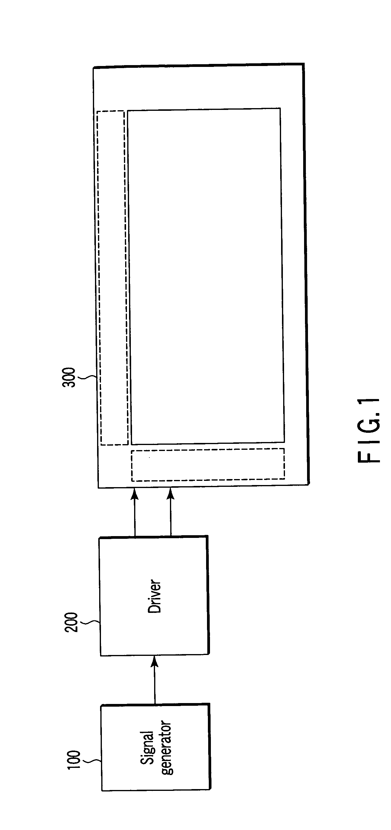
[0023]FIG. 1 schematically shows the overall arrangement of a liquid crystal display device to which the present invention is applied. FIG. 2 is a block diagram of an embodiment of the present invention.

[0024] In FIG. 1, 100 denotes a signal generator which is, for example, a television tuner, a set-top box, a personal computer, or the like and outputs video information. The video information is input to a driver 200 for conversion into a signal for display. The resulting display signal is then applied to a display device 300 which is a liquid crystal display device, for example.

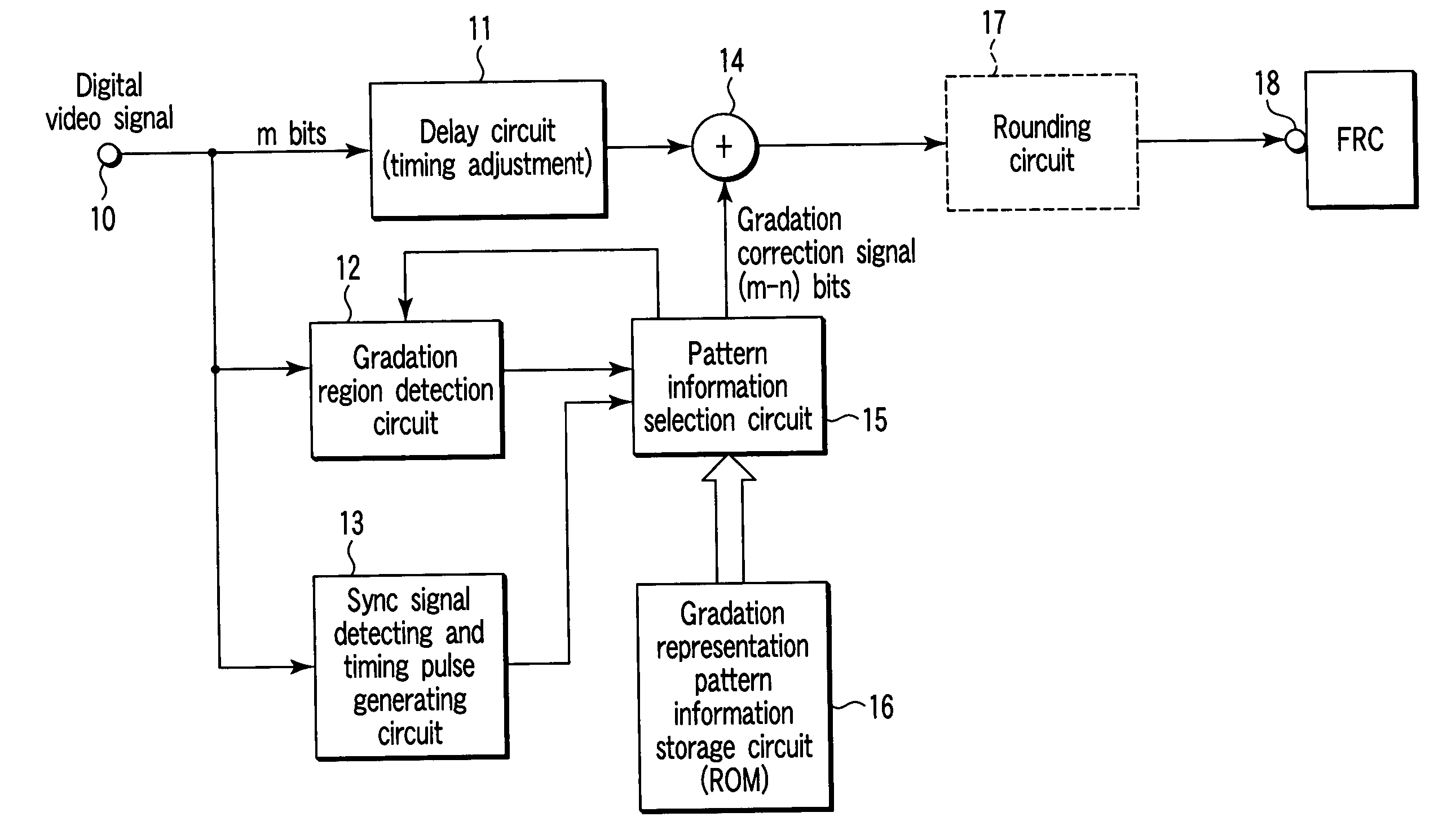
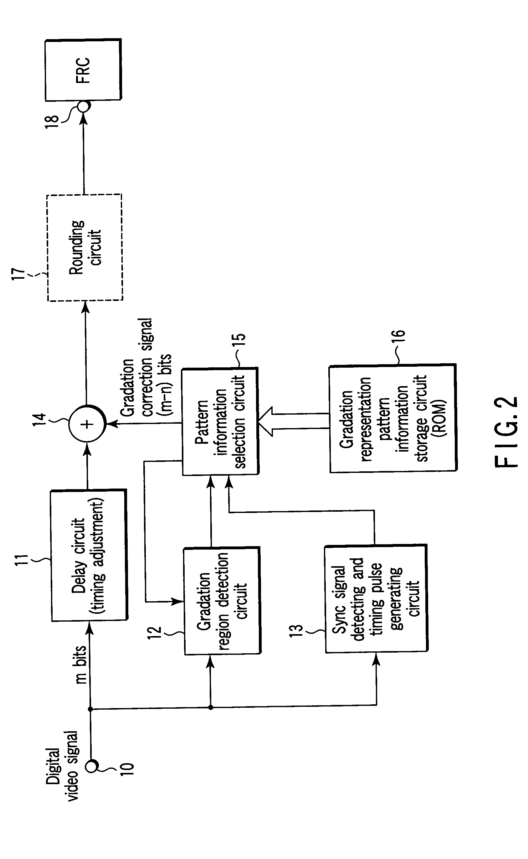
[0025]FIG. 2 is a block diagram of a signal processing unit according to the present invention. The signal processing unit is integrally incorporated into the driver 200 or the display device 300. In FIG. 2, a digital video signal (for example, m bits) is applied through an i...


PUM


Abstract

The gradation representation capability is automatically controlled according to gradation regions and properties (moving or still image) of an input video signal. In a gradation representation pattern information storage circuit is stored a plurality of pieces of gradation representation pattern information which are different in the number of repetition unit frames for gradation representation according to a plurality of degradation regions. One piece of gradation representation pattern information stored in the gradation representation pattern information storage circuit is selected according to a gradation region detected from an input video signal. Gradation representation data of the frame rate corresponding to the selected gradation representation pattern information is output.

Description

CROSS-REFERENCE TO RELATED APPLICATIONS [0001] This application is based upon and claims the benefit of priority from prior Japanese Patent Application No. 2004-128234, filed Apr. 23, 2004, the entire contents of which are incorporated herein by reference. BACKGROUND OF THE INVENTION [0002] 1. Field of the Invention [0003] The present invention relates to a video signal processing device, a display device, a receiver, and a display method which are adapted to perform multi-gradation control through frame-rate control (FRC) using a liquid crystal display device, a plasma display device, or the like. [0004] 2. Description of the Related Art [0005] For example, one method for controlling gradation in liquid crystal display devices is frame-rate control (FRC). In the FRC method, a certain number of frames is set as a unit and the number of times (the number of frames) target pixels are turned on within the frame unit is controlled according to gradation. When the pixels are turned on in...

Claims


Application Information

Patent Timeline
Patent Type & Authority Applications(United States)
IPC IPC(8): G09G3/20H04N5/20G09G5/00H04N5/202
CPCG09G3/2025G09G3/204G09G3/3611G09G2320/103G09G2320/0247G09G2320/0261G09G2320/0219
Inventor MIYAZAWA, HIROTOSHI
Owner KK TOSHIBA
Why Eureka
Try Eureka