
Method and apparatus for discriminating ambient light in a fingerprint scanner

a fingerprint scanner and ambient light technology, applied in the field of fingerprint scanners, can solve problems such as not allowing logs, and achieve the effect of minimizing the effects of ambient light and improving the optical image of fingerprints

Inactive Publication Date: 2005-11-10
CROSS MATCH TECH
View PDF16 Cites 40 Cited by
  • Summary
  • Abstract
  • Description
  • Claims
  • Application Information

AI Technical Summary

Benefits of technology

[0013] A method for obtaining an improved optical image of a fingerprint overcomes degradation of the quality and contrast of the image by minimizing the effects of ambient light. In an exemplary embodiment, the method comprises illuminating an object to be imaged with light that includes a predetermined wavelength, filtering the reflection with a band pass filter that passes the predetermined wavelength, and capturing the image with an image sensor.

Problems solved by technology

If someone else tries to log in as the same person, their biometric information does not fully match, so the system will not allow them to log in.

Method used


Image

  • Method and apparatus for discriminating ambient light in a fingerprint scanner
  • Method and apparatus for discriminating ambient light in a fingerprint scanner
  • Method and apparatus for discriminating ambient light in a fingerprint scanner

Examples


example fingerprint

Scanning System

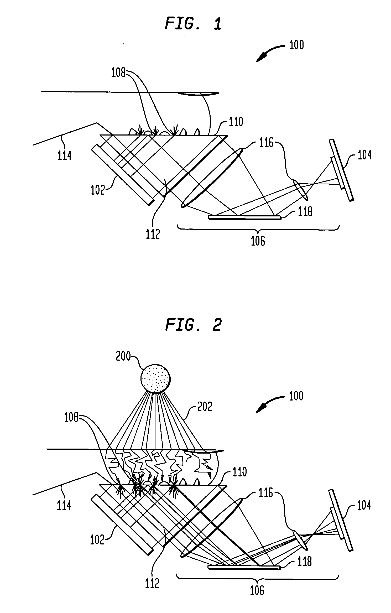
[0034]FIG. 1 is a side sectional view of a prism-type fingerprint scanner 100. In the example shown, an illumination source 102, which may be a green light source, emits light that passes through a prism 112 and is directly imaged onto the image sensor 104 by an optical sub-system 106. Prism 112 has a platen surface 110 against which finger 114 is placed. Finger 114 has fingerprint ridges 108 that contact platen surface 110.

[0035] The fingerprint scanner 100 in FIG. 1 uses total internal reflection (TIR) to capture a fingerprint. TIR is an optical phenomenon. When light crosses media with different refractive indices, the light beam will be bent at the boundary between the two media. At a certain angle of incidence known as the critical angle, light will stop crossing the boundary but instead reflect back internally at the boundary surface. TIR occurs only at a high refractive index or a low refractive index boundary and not the other way around. For example, if the ...

example embodiment

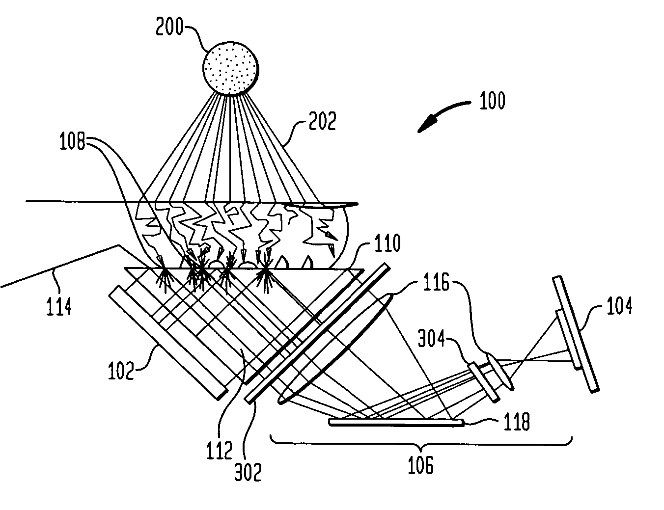
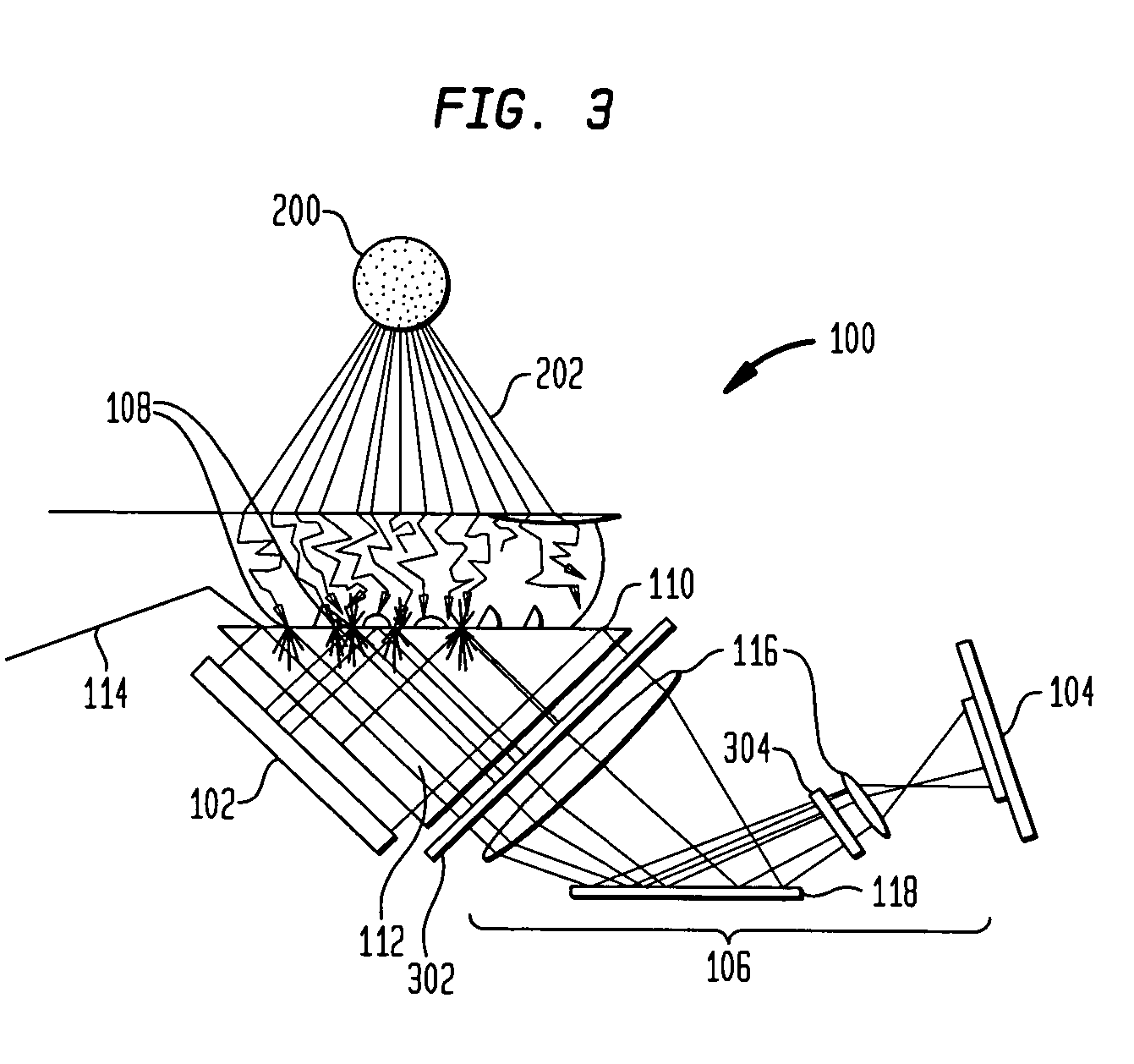
[0039] In one embodiment, the described method operates with a fingerprint scanner using a bright field illumination method. As seen in FIG. 3, in an embodiment that operates effectively with a green illumination source 102, a green band pass filter 302 and an infrared (IR) cutoff filter 304 are provided in optical path 106. The addition of filters in this embodiment prevents the unwanted external ambient light from reaching image sensor 104. Ambient light in the green range will not pass through the finger as these are shorter wavelengths and are absorbed and blocked naturally by the finger 114. Ambient light in the red and infrared ranges have longer wavelengths and will pass through finger 114 but will be substantially attenuated or blocked by band pass filter 302 and IR cutoff filter 304. Thus, image sensor 104 will receive the light reflected from green illumination source 102 without substantial interference from ambient light source 202 or other ambient light sources.

[0040] ...


PUM


Abstract

A surface pattern imaging device applicable to fingerprint and other surface imaging applications operates with an illumination source. In an embodiment, the illumination source is a narrow band green light, and an optical imaging path of the reader includes a green band pass filter and an infrared (IR) cutoff filter between the surface of interest and an image sensor. The filters prevent ambient light outside the green range from reaching the image sensor. In an exemplary embodiment useful in fingerprint imaging, ambient light wavelengths in the green range are absorbed and blocked naturally by the finger, and therefore cannot pass through the finger into the imaging path. Ambient light in other ranges, particularly including the red and infrared ranges which may pass through the finger, is attenuated by the band pass and IR cutoff filters. The image sensor in the improved reader therefore receives the light reflected from the green illumination source, while interference from ambient light sources is substantially attenuated.

Description

CROSS-REFERENCE TO RELATED APPLICATIONS [0001] This application claims the benefit of U.S. Provisional Application Ser. No. 60 / 566,175, filed Apr. 29, 2004, incorporated herein by reference in its entirety.BACKGROUND OF THE INVENTION [0002] 1. Field of the Invention [0003] The present invention relates generally to eliminating the effects of ambient light (indoor or outdoor) on an image. [0004] 2. Background Art [0005] Biometrics is the science and technology of authentication (i.e. establishing the identity of an individual) by measuring the person's physiological or behavioral features. The term is derived from the Greek words “bios” for life and “metron” for degree. [0006] In information technology, biometrics usually refers to technologies for measuring and analyzing human physiological characteristics such as fingerprints, eye retinas and irises, voice patterns, facial patterns, and hand measurements; especially for authentication purposes. [0007] In a typical biometric system,...

Claims


Application Information

Patent Timeline
IPC IPC(8): G06V10/143
CPCG06K9/00046G06K2009/00932G06K2009/0006G06K9/2018G06V40/1341G06V40/1324G06V40/14G06V10/143
Inventor MCCLURG, GEORGE W.CARVER, JOHN F.CANNON, GREGORY L.MCDOW, TIMOTHY S.
Owner CROSS MATCH TECH
Learn More