Method and device for chucking rotationally symmetrical bodies and configuration of the body to be chucked

Inactive Publication Date: 2005-11-10
ABB TURBO SYST
View PDF21 Cites 5 Cited by
  • Summary
  • Abstract
  • Description
  • Claims
  • Application Information

AI Technical Summary

Benefits of technology

[0003] An object of the invention is therefore to specify a method and a device with which rotationally symmetrical bodies can be reproduced and can be clamped coaxially and in a stable manner with high precision. A further object is to p

Problems solved by technology

However, centered clamping of rotationally symmetrical bodies is only possible to a limited extent with these commercially available chucks.
The reproducibility of the clamping process is therefore unsatisfactory as a rule and leads to

Method used


Image

  • Method and device for chucking rotationally symmetrical bodies and configuration of the body to be chucked
  • Method and device for chucking rotationally symmetrical bodies and configuration of the body to be chucked
  • Method and device for chucking rotationally symmetrical bodies and configuration of the body to be chucked

Examples


Example

[0033] The reference numerals used in the drawings and their meaning are compiled in the list of reference numerals.

[0034] In principle, the same parts are provided with the same reference numerals. The embodiment described represents the subject matter of the invention by way of example and has no restrictive effect.

Ways of Implementing the Invention

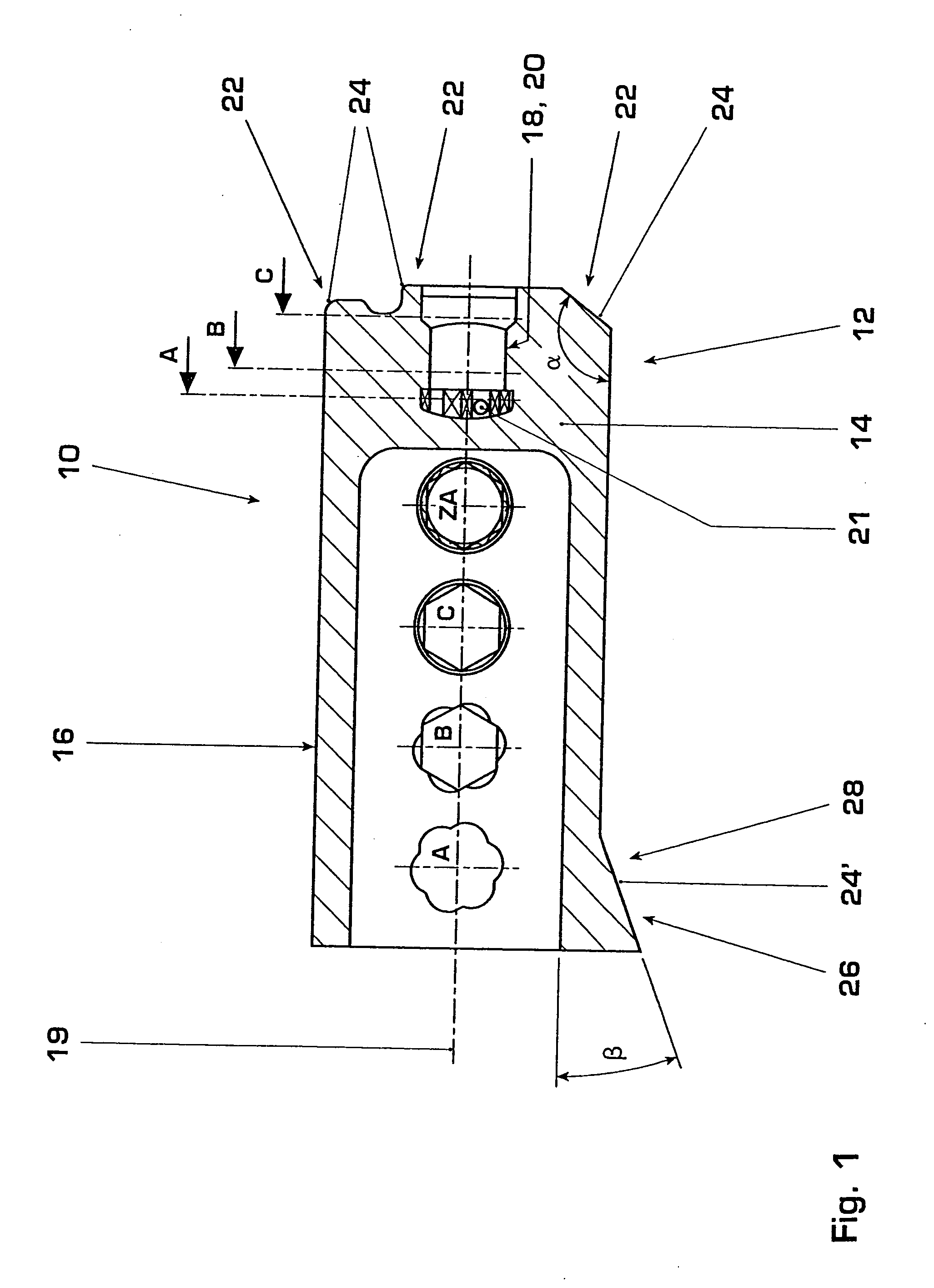
[0035]FIG. 1 shows a rotationally symmetrical body 10 in the form of a hollow cylinder 16 closed on a first side 12 by means of an integrally formed lid 14. The lid 14 on the first side 12 of the body 10 has a coupling unit 18 which extends essentially in the direction of the rotation axis 19 of the rotationally symmetrical body 10. The coupling unit 18 is the first half of the quick-action coupling, which in this example is configured as a bayonet catch 20. The coupling unit 18 can be stressed in tension. It is designed in the form of hollow-cylindrical or hollow-polygonal shapes of different diameter (cf. sections A, B, C, ZA) whi...


PUM

PropertyMeasurementUnit
Forceaaaaaaaaaa
Distanceaaaaaaaaaa
Circumferenceaaaaaaaaaa

Abstract

A method of clamping a rotationally symmetrical body (10) for the purpose of machining, in which method the body (10), with its first side (12), is pulled by means of a tensile force (F1), which acts in extension of the rotation axis (19, 19′) of the body (10) on the first side (12) of the body (10), against a supporting element (72) having a centering effect.
A device for clamping a rotationally symmetrical body (10) for the purpose of machining, which device comprises a supporting element (72), against which the body (10) can be pulled, and a tie rod (64) which can act on and pull the body (10), to be clamped, axially and concentrically to the rotation axis (19, 19′) of the latter. The mounting of the tie rod (64) is designed in such a way that the tie rod (64) is axially guided with radial clearance (66) for the axial pulling movement. The tensile force (F1) of the tie rod (64) is preferably adjustable.
A rotationally symmetrical body (10), in particular a rotor, which, on a first side (12), has a coupling unit (18), which is concentric with its rotation axis (19), and a bearing region (22) having at least three bearing surfaces (24) arranged concentrically to the rotation axis (19).

Description

TECHNICAL FIELD [0001] The invention relates to the field of machining of rotationally symmetrical bodies, specifically rotors, such as compressor wheels, turbine wheels, compressors and the like. In particular, it relates to a method of clamping rotationally symmetrical bodies according to the preamble of the method claim, to a device for clamping rotationally symmetrical bodies according to the preamble of the device claim, and to a rotationally symmetrical body according to the preamble of the object claim. PRIOR ART [0002] Many rotationally symmetrical bodies which are subsequently used in machines or are used in another way, such as, for example, pipes, shafts, spindles, wheels, rotors, are first of all produced in the form of blanks which have the basic shape of the desired body. The blanks may be produced, for example, by casting, sintering, die-casting, forging, etc. In order to give the blanks the desired final shape, subsequent machining is usually still required, such as,...

Claims


Application Information

Patent Timeline
IPC IPC(8): B23B31/02B23Q1/00B23Q3/18F04D29/28
CPCY10T409/303808F04D29/284
Inventor MUELLER, ALFREDKNECHT, FRANZ
Owner ABB TURBO SYST
Why Eureka
Try Eureka