Crankshaft production machine

A technology of crankshaft processing and crankshaft, which is applied in the direction of metal processing machinery parts, metal processing, metal processing equipment, etc., can solve the problems such as the decrease of the stability of the milling unit itself, the unimaginable high precision processing of the workpiece, and the limited surface quality of the workpiece. Achieve high stability, eliminate gaps, and high rigidity

Inactive Publication Date: 2010-09-22
NILES SIMMONS INDUSTRIEANLAGEN GMBH
View PDF5 Cites 1 Cited by
  • Summary
  • Abstract
  • Description
  • Claims
  • Application Information

AI Technical Summary

Problems solved by technology

As a result, it is difficult to imagine machining workpieces with a high degree of precision, since in particular the achievable sur

Method used


Image

  • Crankshaft production machine
  • Crankshaft production machine
  • Crankshaft production machine

Examples


Embodiment Construction

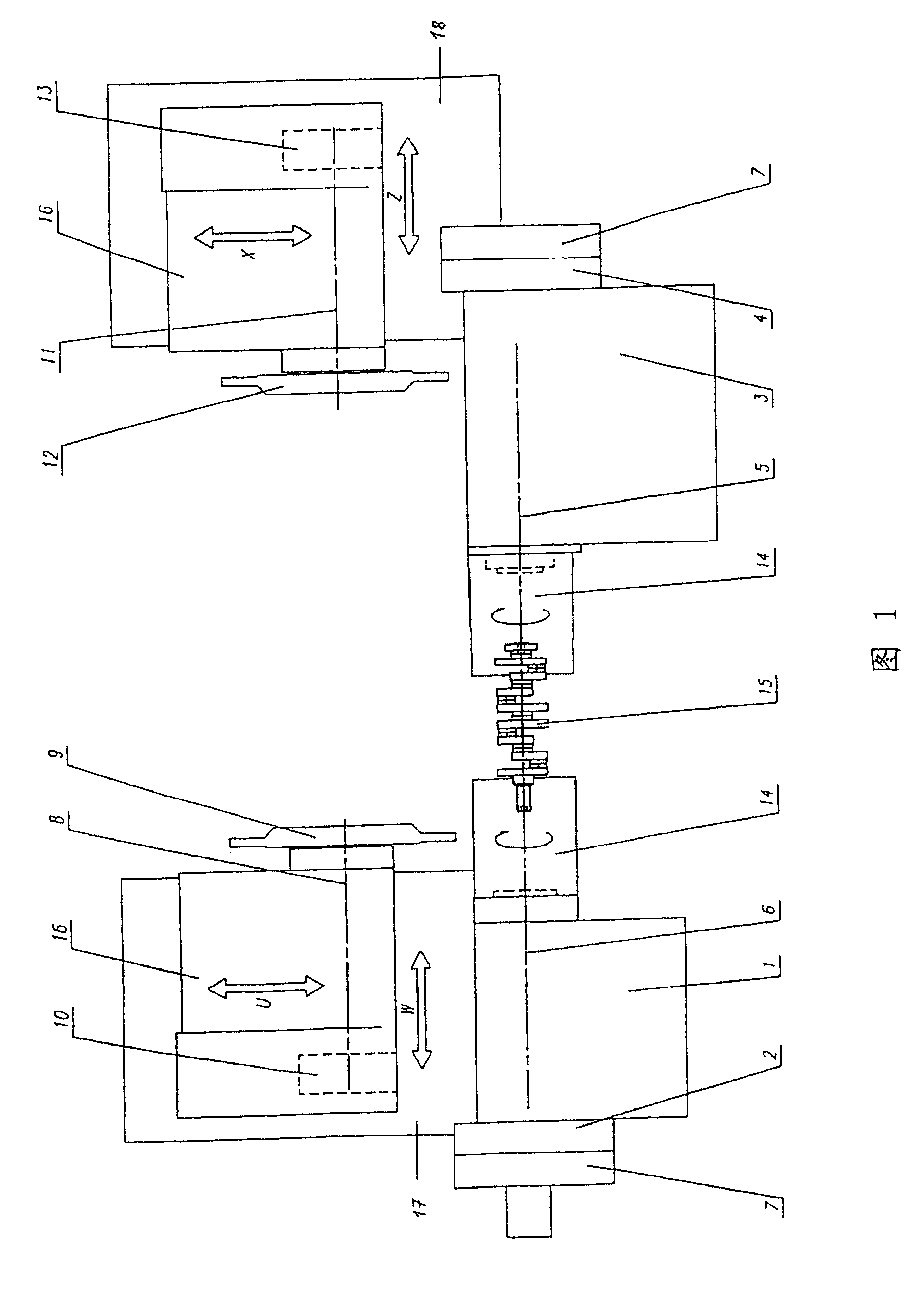
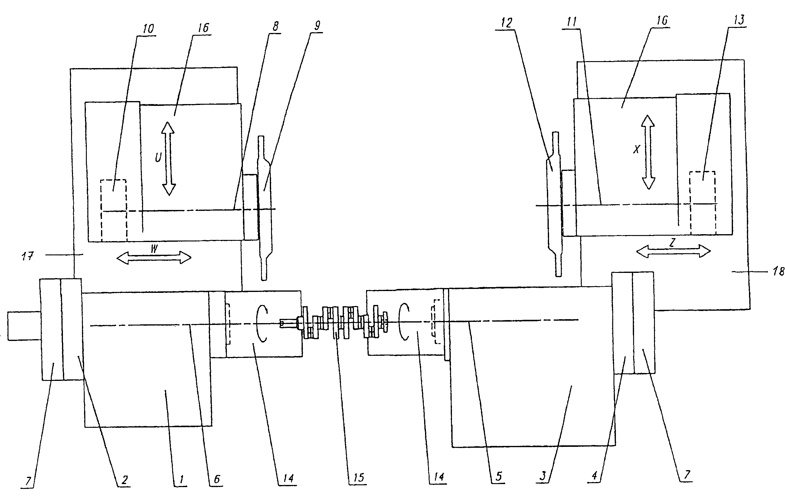
[0020] figure 1 shows a crankshaft machining machine with a headstock. The headstock has a first workpiece spindle 1 which is rotatable about a C-axis 6 . Corresponding to the spindle box, there is also a torque motor 2 as a spindle drive device. The axis of the motor 2 coincides with the gripper axis 6 . A measuring system 7 is an integral component of the positionally adjustable spindle drive. In contrast, a torque motor 4 with an integrated C-axis 5 is provided as drive on a counter spindle with a second workpiece spindle 3 . The control of the crankshaft processing machine allows electronic synchronization of the above-mentioned two workpiece spindle drives.

[0021] The workpiece 15 to be machined in the form of a crankshaft is clamped by means of the clamping device 14 .

[0022] The crankshaft machining machine includes two milling units. On the two longitudinal slides or slides 17 and 18 displaceable in the Z and W directions of the two milling units there is a t...


PUM


Abstract

The invention relates to a crankshaft production machine for producing crankshafts (15), which have centric and eccentric surfaces to be machined and which are held in a manner that enables them to rotate about a C axis (5, 6). Said machine comprises a headstock, a counter spindle or a tailstock, at least one displaceable longitudinal slide (17, 18) and drive units having motors for driving the crankshaft about the C axis and for advancing subassemblies for tool spindles (8, 11) and the tools. The motor in at least one drive unit, which serves to drive tool spindles (1, 3), and in at least one drive unit, which serves to drive tool spindles (8, 11), is provided in the form of a torque motor (2, 4, 10, 13).

Description

technical field [0001] The invention relates to a crankshaft machining machine for producing crankshafts with concentric and eccentric surfaces to be machined, which are clamped rotatably about a C-axis. Background technique [0002] A turning / milling machine for machining workpieces with concentric and eccentric surfaces to be machined, in particular crankshafts, has a headstock with drive units and electric motors for driving the workpiece in rotation about the C-axis counterspindle or tailstock, at least one drive unit with component feed for the tool spindles and a movable longitudinal slide with these tools. These turning / milling machines therefore include in particular at least one drive unit for the rotary movement. Such drive units are to be understood as those drive units which are required in particular for components for driving tool and workpiece (e.g. lathe spindle, C-axis) and those for machining concentric and eccentric workpiece surfaces (e.g. crankshaft sur...

Claims


Application Information

Patent Timeline
IPC IPC(8): B24B19/12B23Q5/28B23Q5/10B23B5/18B23Q5/04B23Q39/04
CPCB23B5/18B23Q5/04B23Q39/048B23Q5/10Y10T409/307168Y10T29/17Y10T409/403325Y10T82/19Y10T409/305712Y10T29/5114Y10T409/30756Y10T82/2508
Inventor 莱因哈德·罗博塔冈特·施罗特
Owner NILES SIMMONS INDUSTRIEANLAGEN GMBH
Why Eureka
Try Eureka