
Device for fixation of door on HVAC for automobile

a technology for fixing devices and automobiles, which is applied in lighting and heating apparatus, drying machines, and drying machines with progressive movements. it can solve problems such as abnormal noise (air current noise) problems, affecting the working of air/heating in the automobile hvac system, and affecting the air/heating function of the automobil

Inactive Publication Date: 2005-11-10
MODINE KOREA
View PDF11 Cites 5 Cited by
  • Summary
  • Abstract
  • Description
  • Claims
  • Application Information

AI Technical Summary

Benefits of technology

[0008] As described before, this invention has been developed to improve the existing problems. The purpose of this invention is to provide a door fixation apparatus for a vehicle air conditioner, which prevents partial openings of various doors and dampers that are attached in the air conditioner by wind pressure when a vehicle or the air conditioner is operated and when the doors or dampers are closed.

Problems solved by technology

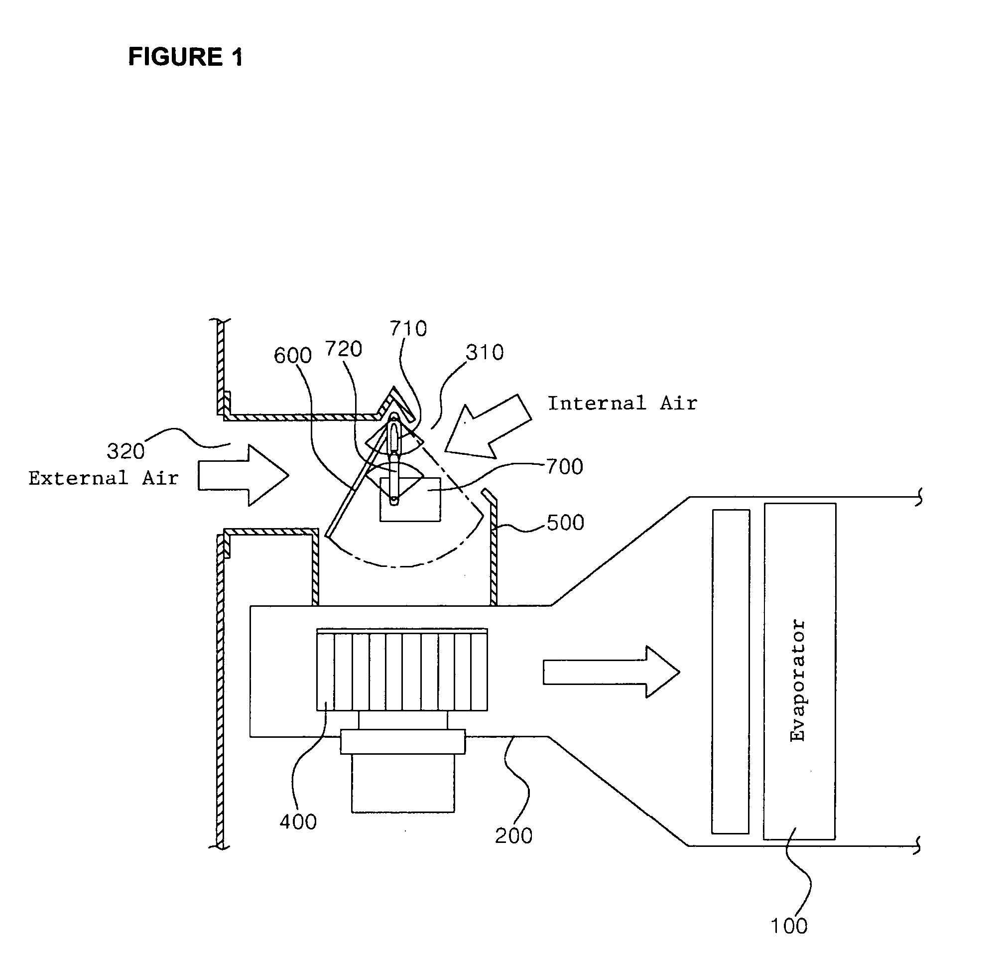
However, if the automobile is moving at a high speed while in the internal circulation mode, the exterior air pressure applies force onto the external air entry (320), partially opening the air intake door (600) that was shielding the external air entry (320), and causing the entry of external air through the opening crack.
Consequently, the opening crack suctions in air pressure and causes not only the abnormal noise (air current noise) problem, but decreases air / heating functioning in the automobile HVAC system.
Furthermore, when the automobile is on external air intake mode, the air intake door (600) which was shielding the internal air entry (310) is forced open by the suction pressure from the blower (400), thus causing noise as previously described.
It was difficult to solve the above-described problems completely with these changes, and, due to the limited space, difficulty to apply these changes continued.
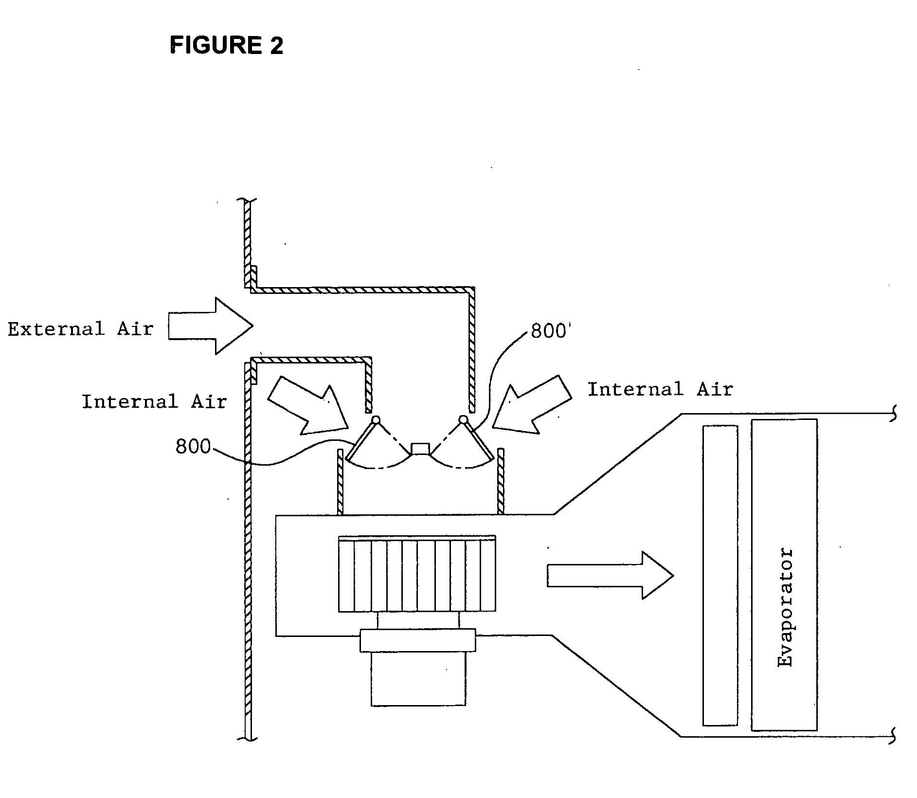
Further, as explained with FIG. 1 for the air intake door, the previously described problems are common with the automobile ventilator's wind amount controlling door, the temperature controlling door, and the wind direction controlling door or the dampers.

Method used


Image

  • Device for fixation of door on HVAC for automobile
  • Device for fixation of door on HVAC for automobile
  • Device for fixation of door on HVAC for automobile

Examples


Embodiment Construction

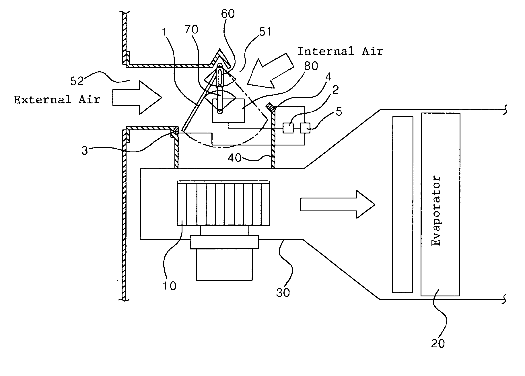
[0015] The attached FIG. 3 illustrates the invention's applicable example of a door fixation apparatus and its related devices that attach the air intake door to the HVAC system.

[0016] As shown, an air intake case (40) is mounted on the HVAC case (30) to which a blower (10) and an evaporator (20) are installed to draw vehicle internal / external air, and this air intake case (40) is installed with an air intake door (1) that opens and closes the ventilator selectively for internal air entry (51) and external air entry (52). This air intake door (1) is operable in the opening / closing of the above internal / external entry (51,52) by connecting to the actuator (80) through the lever (60) and link material (70), when the actuator (80) is activated. Also, the actuator (80) is connected to the controller (2) so that the vehicle operator can control its activation accordingly. The controller (2) consists of a general microcomputer.

[0017] This invention's door fixation apparatus is comprised...


PUM


Abstract

The present invention relates to a door fixation apparatus for a vehicle air conditioner that is capable of preventing various doors or dampers that are installed in an air conditioner from partially opening due to wind pressure when a vehicle is operating or an air conditioner is operated in a state that the doors or dampers are closed. The door fixation apparatus includes a magnetic body that forms at least part of a ventilation opening and closing of the door of the vehicle air conditioner; an electromagnet that is installed adjacent a ventilation opening so that at least part of the magnetic body of the door is magnetically adhered to the electromagnet in a blocking position of the ventilation opening; a power source that supplies the current for magnetizing the electromagnet; and a controller to judge the opening and closing state of the ventilation opening and control a current supply of the power source.

Description

FIELD OF THE INVENTION [0001] The present invention relates to a door fixation apparatus of automobile air conditioner technology, which prevents the movement of the various doors (or dampers) by wind pressure that are installed in an air conditioner air intake apparatus or duct to control the internal / external air changes and the wind amounts. BACKGROUND OF THE INVENTION [0002] The automobile's HVAC (Heating, Ventilating & Air Conditioning) system for the cold / warm air control comprises the heat exchanger and blower units. It is operated by flowing cold / warm air or ventilation through the duct that is connected from the vehicle's exterior to the interior. [0003] The attached FIG. 1 illustrates an air intake part of this HVAC system to which an evaporator (100), situated in the HVAC case (200) supplies the internal / external air inward. As shown, inside of HVAC case (200) is installed with an evaporator (100) and a blower (400) in the direction of internal / external air entry (310,320...

Claims


Application Information

Patent Timeline
IPC IPC(8): B60H1/00B60H1/12B60H1/24B60H1/26F16K35/16
CPCB60H1/00678B60H2001/00714B60H1/00849F26B5/06F26B5/12F26B15/18F26B21/004F26B2200/16F26B2210/02
Inventor KIM, MAN HEE
Owner MODINE KOREA
Learn More