Helmet cushioning pad with variable, motion-reactive applied-load response, and associated methodology

a technology of adaptive padding and adaptive padding, applied in the field of human body protective and cushioning helmet interface (shock absorption) structure, can solve the problems of reducing the likelihood of serious injury, poor job, and many complaints from users, and achieves significant anti-injury impact delivery

Inactive Publication Date: 2005-11-17
MJD INNOVATIONS
View PDF99 Cites 21 Cited by
  • Summary
  • Abstract
  • Description
  • Claims
  • Application Information

AI Technical Summary

Benefits of technology

[0012] The association which exists, according to the present invention, between the load-cushioning pad structure and a helmet shell, is that the helmet shell converts whatever kind of specific impact occurs to it from the outside to a broad-area, blunt-trauma kind of event which is delivered directly to the load-cushioning pad structure without there being any interposed, other load-managing material, such as any material with springy rebound (resilience) behavior. Such a blunt-trauma event presented through the shell to the load-cushioning structure takes maximum advantage of the cushioning capabilities of the load-cushioning structure, and results in significant anti-injury impact delivery to the head of a helmet wearer.

Problems solved by technology

Airspace between the webbing and the shell of the helmet contributes somewhat to the ballistic, and significantly to the cooling, capabilities of the helmet, but such a webbing system has proven consistently (a) to do a poor job of cushioning shock loads delivered to the wearer's head through the subject helmet, and (b) to be quite uncomfortable, and thus to be the source of many complaints from users.
This behavior, in the “world” of a helmet shell, causes a shock load to be transmitted to, and borne by, the wearer's head over a relatively wide surface area, and thus generally reduces the likelihood of serious injury.
Such a blunt-trauma event presented through the shell to the load-cushioning structure takes maximum advantage of the cushioning capabilities of the load-cushioning structure, and results in significant anti-injury impact delivery to the head of a helmet wearer.

Method used


Image

  • Helmet cushioning pad with variable, motion-reactive applied-load response, and associated methodology
  • Helmet cushioning pad with variable, motion-reactive applied-load response, and associated methodology

Examples


Embodiment Construction

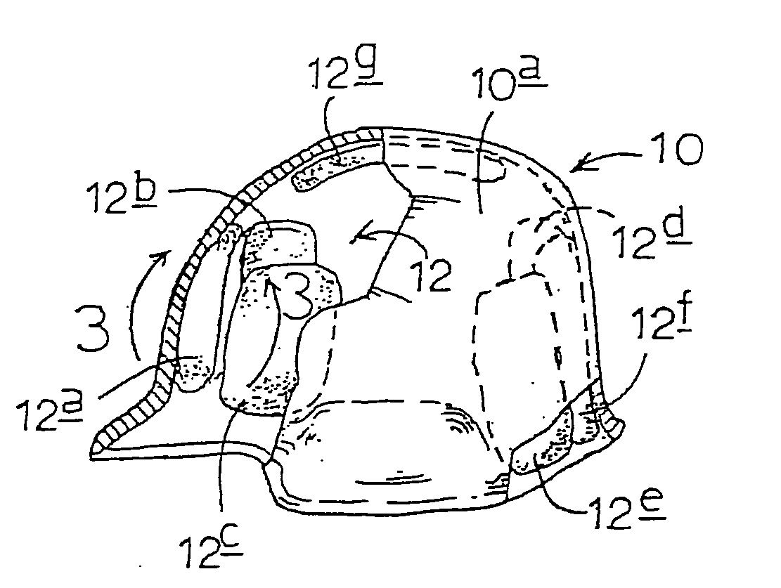
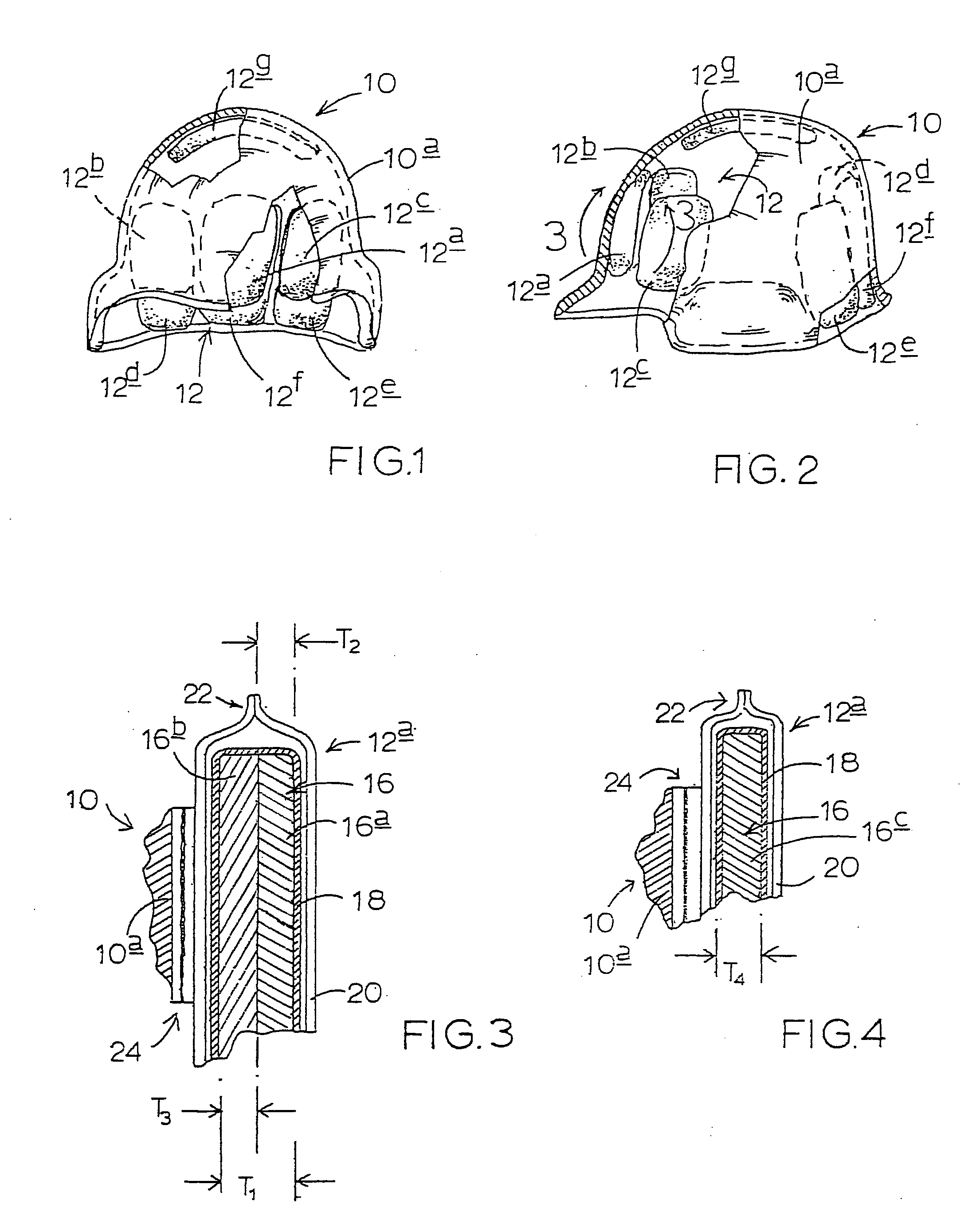
[0020] Turning attention now to FIGS. 1, 2 and 3, indicated generally at 10 is a military helmet including a shell 10a. In all respects, shell 10a is completely conventional in construction, and might have any one of a number of different specific constructions and configurations.

[0021] Fastened in one of a variety of appropriate manners on the inside, concave, dome-like surface of shell 10a is an installation 12 of inside-site-selectable, shock-absorbing, load-cushioning pad structures constructed and operable in accordance with the present invention. Installation 12, in the particular setting illustrated in these figures and now being described, includes seven, individual, multi-layer, load-cushioning pad structures, or pads, 12a, 12b, 12c, 12d, 12e, 12f, 12g, each of which includes one preferred form of a central, or core, load-cushioning instrumentality possessing certain characteristics which are key to the structure and functionality of the present invention. Pad 12a is joine...


PUM

PropertyMeasurementUnit
acceleration-rateaaaaaaaaaa
energy-absorption characteristicsaaaaaaaaaa
hardnessaaaaaaaaaa

Abstract

A site-selectable, helmet-installable load-cushioning pad structure employable inside a helmet shell as a part of a plural-spaced-pad distribution featuring a compressible viscoelastic foam core which resists rapid, but not slow-movement, compression. Associated methodology includes the steps of providing such a structure for installation inside the shell of a helmet, and pre-arming the core of that structure with a load-response characteristics which (a) resists sudden-movement, rapid compression, yet (b) offers less resistance to slow-movement compression. An encapsulating moisture barrier layer may be provided around the foam core.

Description

CROSS REFERENCES TO RELATED APPLICATIONS [0001] This application is a continuation from currently co-pending U.S. patent application Ser. No. 10 / 156,074, filed May 27, 2002 for “Body-Contact Protective Interface Structure and Method”, which application is a continuation from U.S. patent application Ser. No. 09 / 942,987, filed Aug. 29, 2001, entitled “Body-Contact Cushioning Interface Structure and Method”, which is a continuation from U.S. patent application Ser. No. 09 / 390,518, filed Sep. 3, 1999, entitled “Body-Contact Cushioning Interface Structure”, which application claims priority to U.S. Provisional Application Ser. No. 60 / 099,208, filed Sep. 3, 1998, entitled “Body Contact System and Structure for Wearable Garments, such as a Helmet.” The disclosure contents of each of these prior-filed patent applications are hereby incorporated herein by reference.BACKGROUND AND SUMMARY OF THE INVENTION [0002] The present invention relates to a human-body protective, cushioning helmet inter...

Claims


Application Information

Patent Timeline
Patent Type & Authority Applications(United States)
IPC IPC(8): A42B3/12B32B3/26B32B25/08B32B33/00
CPCA42B3/12A42B3/121A42B3/125B32B33/00B32B3/26B32B25/08A42B3/127B32B2307/724B32B2307/7246B32B2437/04Y10T428/249953
Inventor DENNIS, MICHAEL R.TUCKER, MICHAEL W.PAASCHE, GERHARD
Owner MJD INNOVATIONS
Why Eureka
Try Eureka