
Under deck drainage system

Inactive Publication Date: 2005-11-17
KINDRED DAVID J
View PDF14 Cites 16 Cited by
  • Summary
  • Abstract
  • Description
  • Claims
  • Application Information

AI Technical Summary

Benefits of technology

[0013] Each drainage panel has a downwardly extending arcuate cross-sectional configuration and a width sufficient to fastenably extend between the fastening arms of a pair of opposed cooperating fastening brackets. Each side edge of the drainage panel defines at least one tooth-like ridge angulated inwardly away from the fastening bracket to carry it to cooperate with the fastening ridges defined by the adjacent fastening bracket arms to allow the edge of the drainage panel to be moved inwardly between the fastening bracket arms but prevent outward motion of the panel edge, once installed, from between the fastening arms.
[0014] The upper edge portion of the side of the fastening bracket body adjacent a supporting joist may carry a strip of adhesive sealant to aid in temporarily positionally maintaining the fastening bracket on the supporting joist while the fastening bracket is being permanently fastened and to further aid in sealing the adjacent surfaces of the fastening bracket body and the supporting joist.
[0018] A further object is to provide such a drainage system that has elongate fastening brackets with a curvilinear body extending in its medial portion away from the supporting joist to selectively carry adhesive caulking material between the joist and the upper portion of the fastening bracket body to aid sealing of the interface between the joist and upper portion of the body and to temporarily positionally maintain the fastening bracket on the joist to aid permanent fastening.
[0020] A further object is to provide such a drainage system having fastening arms, at least one of which has a plurality of spaced angulated tooth-like ridges extending parallel its length to receive at least one angulated tooth-like interfitting ridge defined in the edge portion of a drainage panel to be carried thereby to allow the drainage panel to be moved inwardly between the fastening arms but prevent the drainage panel from being accidently moved outwardly from therebetween.
[0023] A still further object is to provide such a drainage system that is of rugged and durable nature, of simple and economic manufacture, of easy installation and maintenance and otherwise well suited to the uses and purposes for which it is intended.

Problems solved by technology

Such deck construction has become popular in modern light frame architecture, but notwithstanding its popularity this deck construction commonly limits and disrupts the use of space beneath an elevated deck, which often is not desirable.
Despite the lengthy developmental history of solutions to under deck drainage problems, the past solutions have not adequately nor completely resolved all problems and various problems still remain.
Principal among problems remaining with prior under deck drainage systems are firstly, that such drainage systems are not sealed, or if sealed are not adequately sealed, so as to prevent leakage from the drainage system either on the surface beneath the serviced decks or on the deck structures that support the drainage system and secondly, that such drainage systems are difficult to install and positionally maintain in operative mode in either new construction or especially in existing construction.
Previously existing under deck drainage systems that have provided paired opposed strip type fastening brackets carrying a drainage panel therebetween generally have not provided water impervious joints between the bracket strips and the drainage panel, but rather have relied only on the gravity influenced motion of fluid to prevent leakage between the interconnected adjacent surfaces of the fastening bracket strips and the drainage panels.
An additional problem associated with prior under deck drainage systems, and especially those of a retrofittable type, has been the difficulty of installation which in the past has generally been accomplished by professional mechanics and has required the expenditure of substantial time and effort.
This potential problem is generally greater in direct proportion to the efficiency of the seal between the drainage panel and its associated fastening brackets, and well may be at least one reason that various prior under deck drainage systems have not provided such a seal or at least such an efficient seal.

Method used


Image

  • Under deck drainage system
  • Under deck drainage system
  • Under deck drainage system

Examples


Embodiment Construction

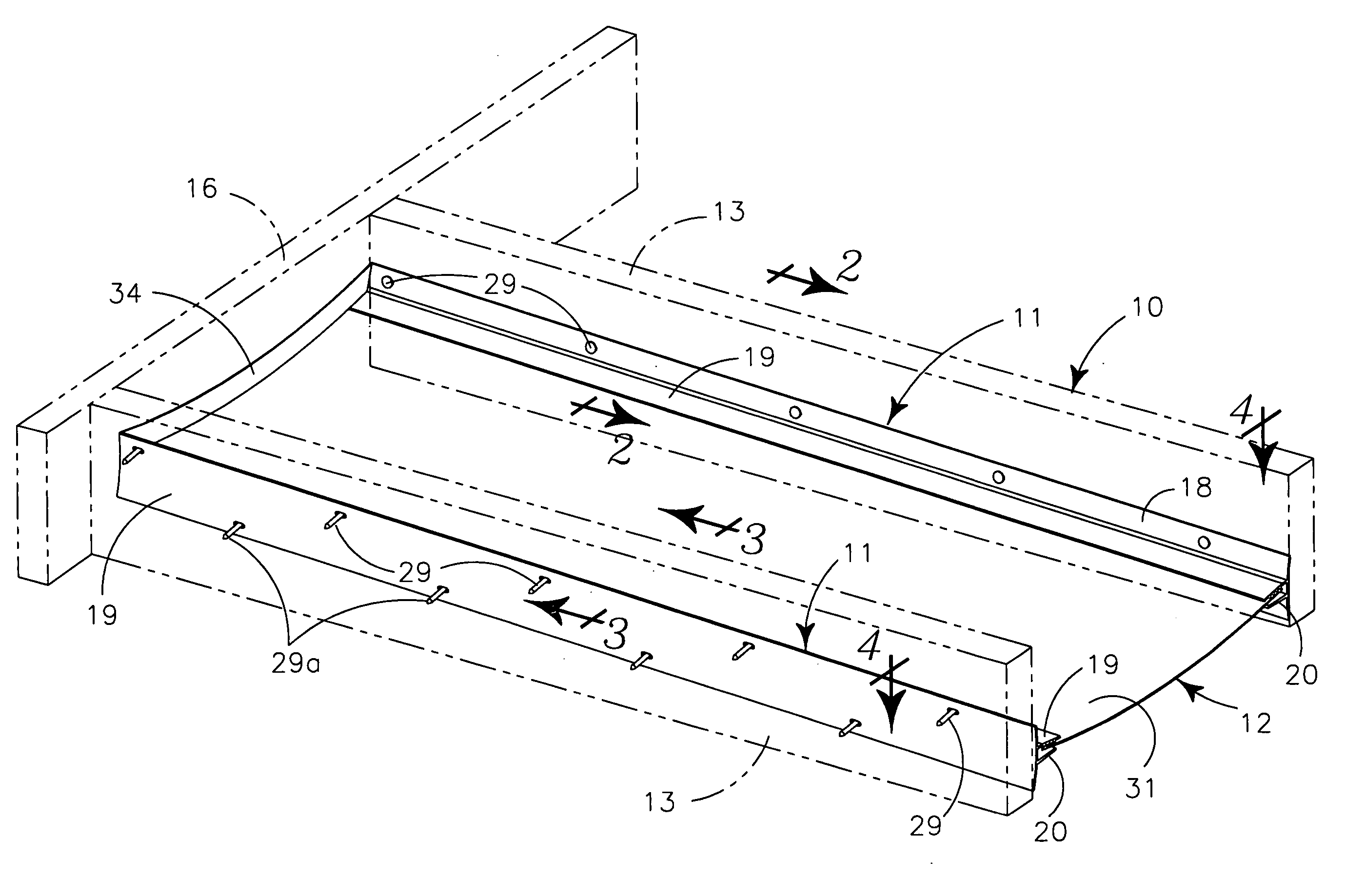
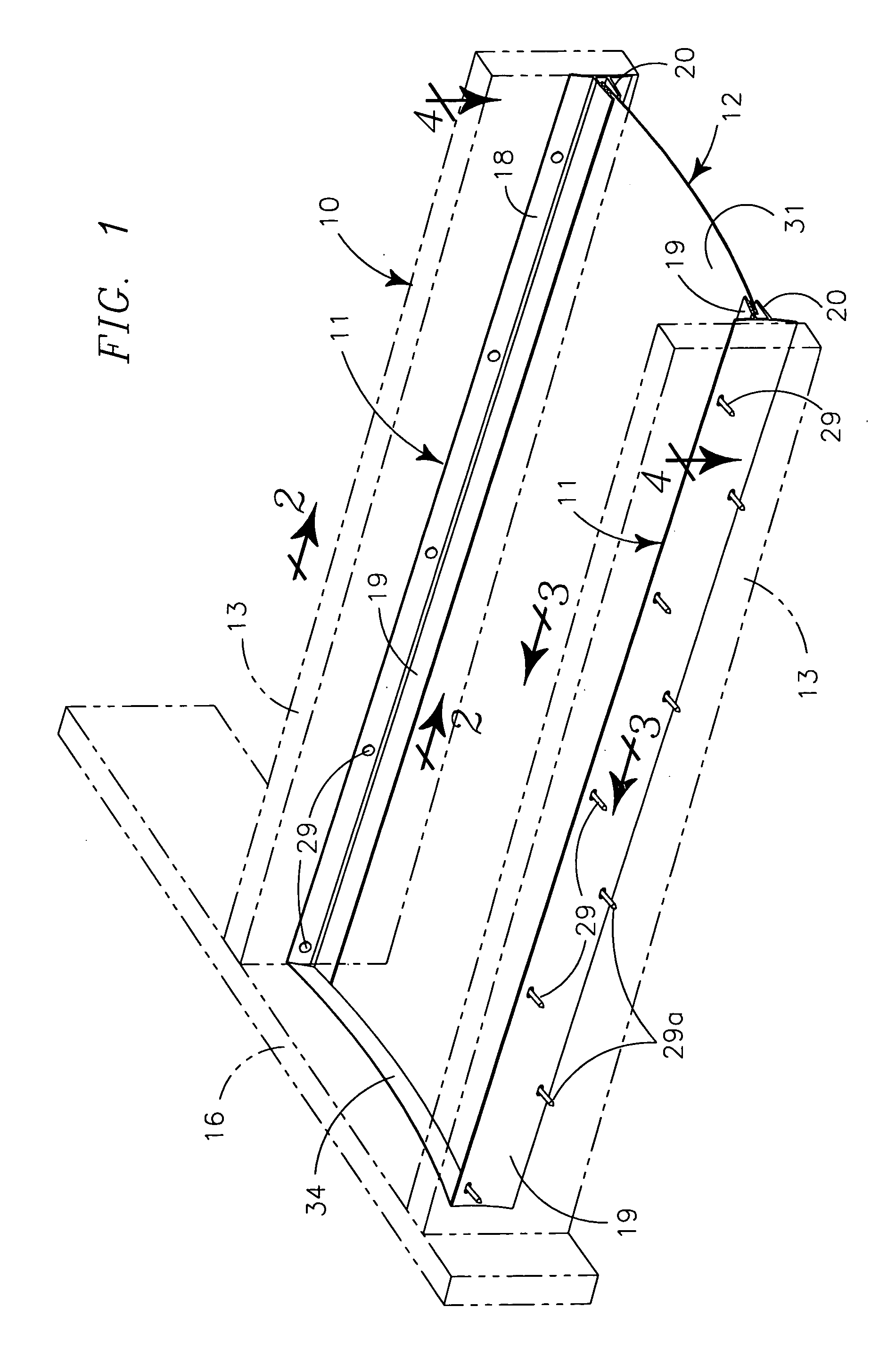
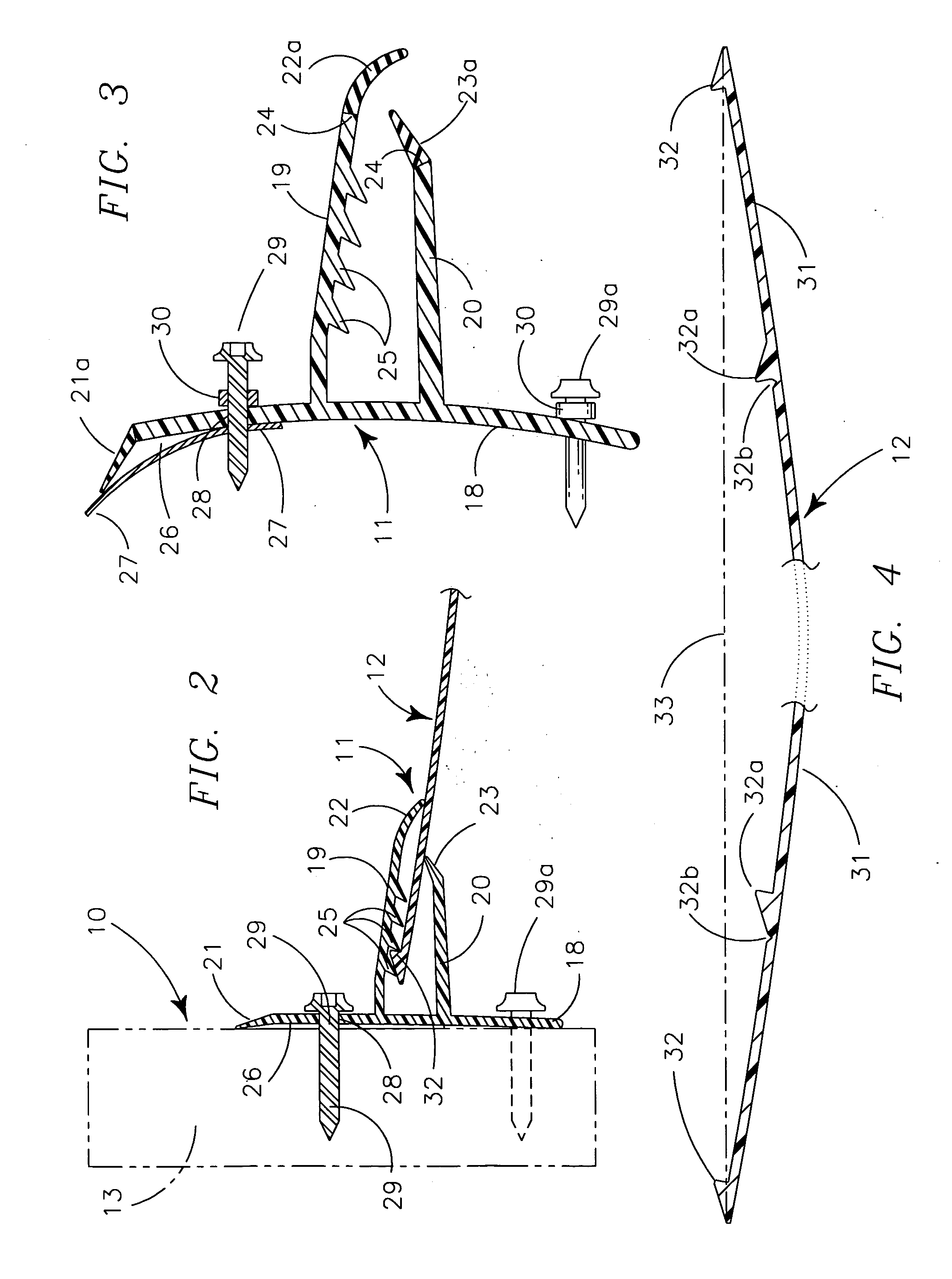
[0031] My invention generally provides a plurality of elongate fastening brackets 11 supported in cooperating pairs on adjacent vertical surfaces of each adjacent pair of joists of deck 10 to carry drainage panels 12 between each cooperating pair of the fastening brackets 11 to drain fluidic material passing downwardly through the surface of deck 10 and transport the drained fluidic material to a deck edge at the outer ends of the joists for further disposition.

[0032] A portion of the type of deck 10 with which my drainage system may be used is shown in FIGS. 1 and 5. The deck 10 provides a plurality of parallel spaced joists 13, extending outwardly from support on an associated support structure (not shown) that extends spacedly above the earth or other supporting structure beneath the deck. The joists 13 normally extend substantially perpendicularly outwardly from the associated support structure and may be supported in cantilever fashion from the associated support structure, by...


PUM


Abstract

An under deck drainage system for a fluidly pervious deck of light frame construction provides paired spacedly opposed elongate fastening brackets, carried on adjacent surfaces of opposed pairs of deck supporting joists, with a downwardly curving drainage panel extending therebetween to receive and transport drainage to a deck edge perpendicular to the joists. The fastening brackets are sealed against the joists carrying them and provide two vertically spaced fastening arms that sealably engage the edges of the drainage panel carried therebetween in a releasable, positionally maintainable interconnection of opposed tooth-like fastening ridges carried by the drainage panel edges and the fastening arms.

Description

BACKGROUND OF INVENTION RELATED APPLICATIONS [0001] There are no applications related hereto heretofore filed in this or in any foreign country by the Applicant. FIELD OF INVENTION [0002] My invention relates generally to light frame structures and more particularly to a drainage system for placement under a fluidly pervious deck to remove drainage from beneath the deck to an outer deck edge. BACKGROUND AND DESCRIPTION OF PRIOR ART [0003] Decks in light frame construction commonly are supported spacedly above a surface such as from the floor level of a half or second story of a main structure having its first story at or below earth level. Such decks are commonly formed with spaced horizontal joists extending outwardly from the main structure to support surfacing boards extending angularly to the joist in a closely spaced array so that fluidic and other smaller solid environmental debris may passed downwardly through spaces between the surfacing boards to be wasted in some fashion b...

Claims


Application Information

Patent Timeline
IPC IPC(8): E04D1/36E04D13/04E04F17/00
CPCE04F17/00E04D13/0477
Inventor KINDRED, DAVID J.
Owner KINDRED DAVID J
Features
  • Generate Ideas
  • Intellectual Property
  • Life Sciences
  • Materials
  • Tech Scout
  • Unparalleled Data Quality
  • Higher Quality Content
  • 60% Fewer Hallucinations
Learn More