Automobile body dent repair tool

Inactive Publication Date: 2005-11-17
FREDENBERG GAGIK M +1
View PDF0 Cites 16 Cited by
  • Summary
  • Abstract
  • Description
  • Claims
  • Application Information

AI Technical Summary

Benefits of technology

[0027] The new fender dent repair tool is a heavy duty puller which uniquely has a second handle near the working tip. The seco

Problems solved by technology

Failing to achieve complete success with these techniques, the dent was finished by filling with lead or epoxy-like plastics.
The resulting work left a damaged or unpainted surface required repainting of the panel and all the attendant problems of matching colors, surface characteristics, etc., followed over time, by differential fading and weathering.
Which is not only costly, the tools cannot be bent to suit the immediate t

Method used


Image

  • Automobile body dent repair tool
  • Automobile body dent repair tool
  • Automobile body dent repair tool

Examples


Embodiment Construction

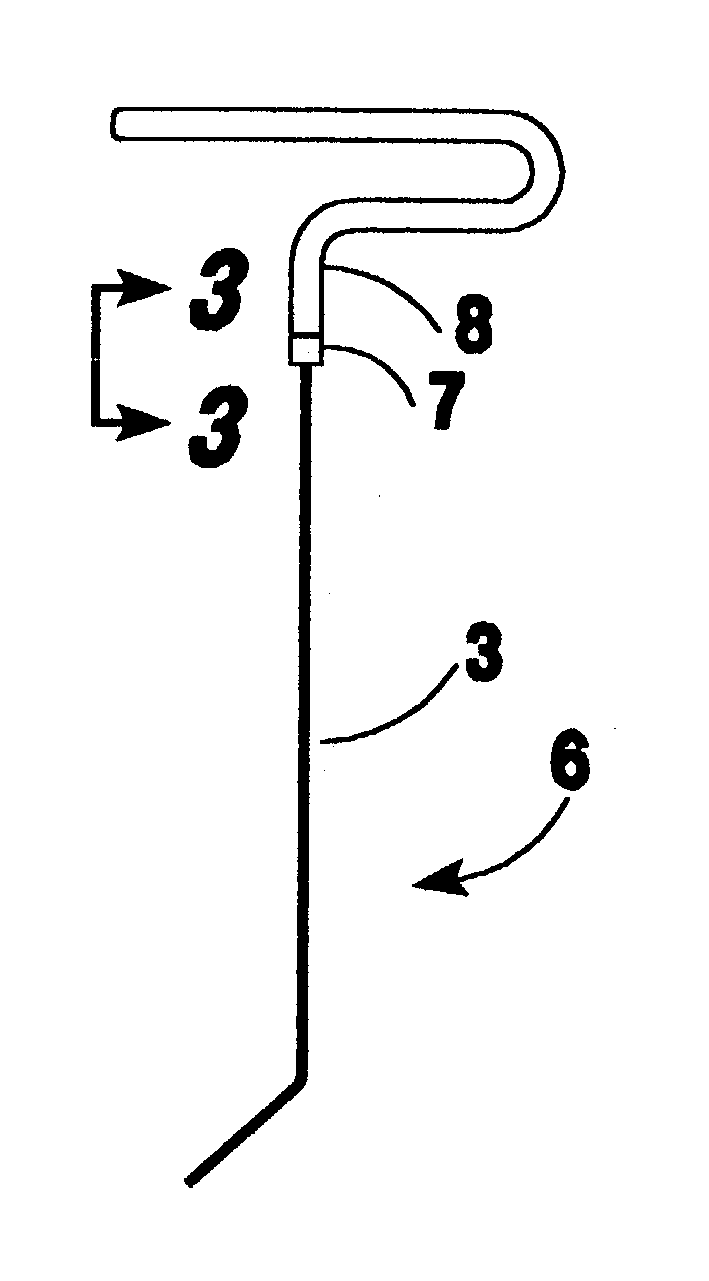
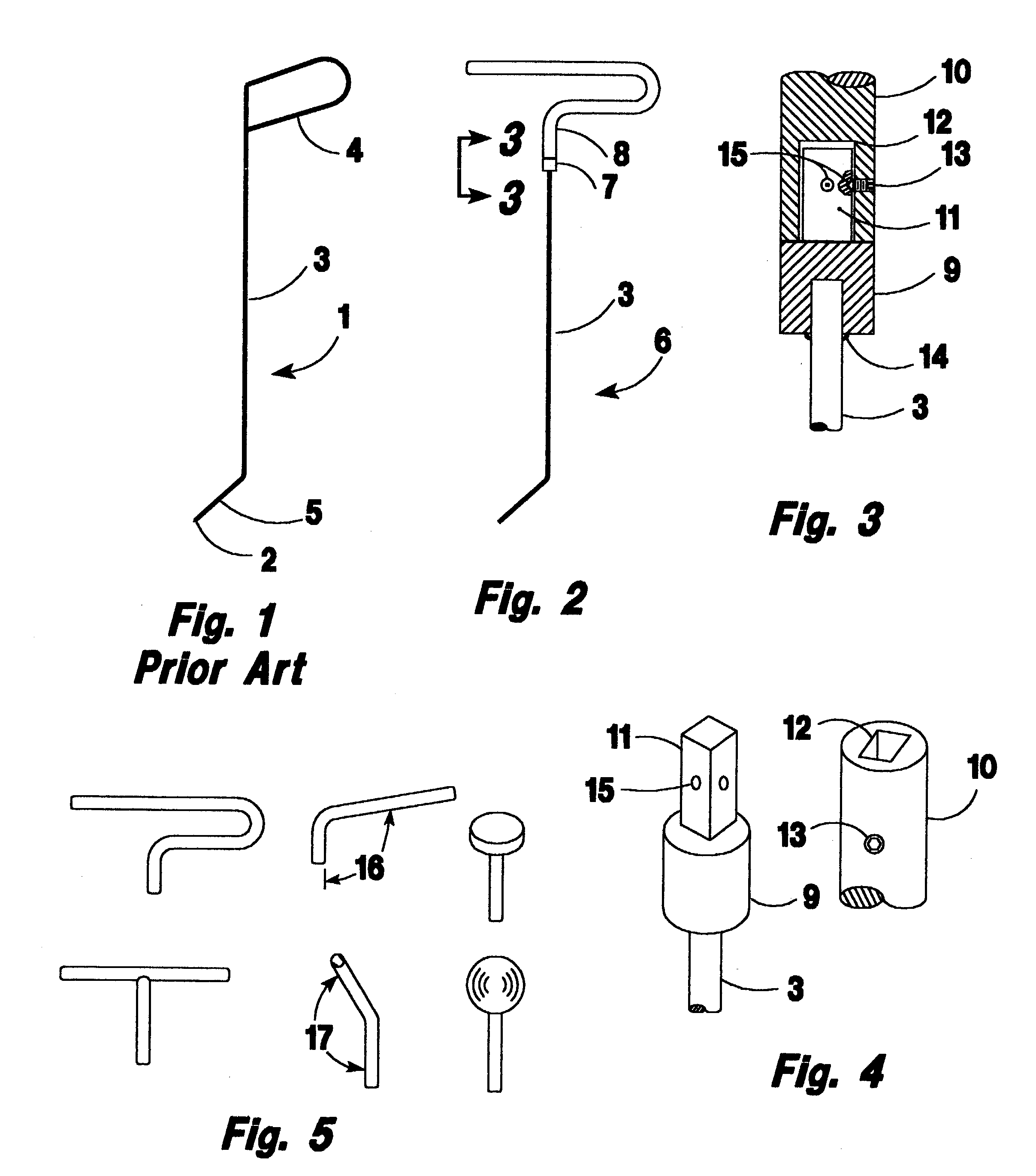
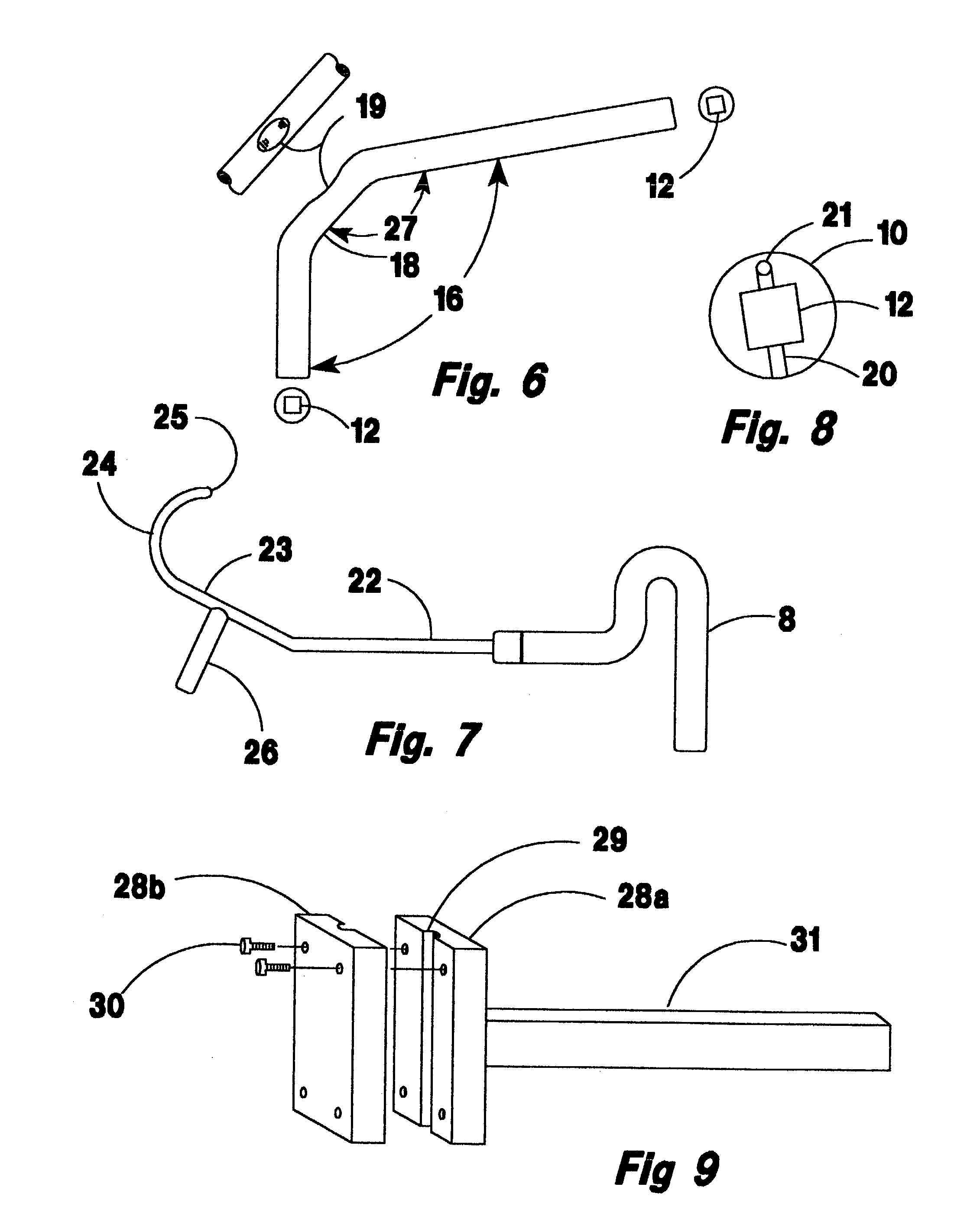
[0069]FIG. 1 is representative of a typical paintless dent repair tool (1) in the prior art It is comprised of three essential parts, a working tip 2 at the distal end, a long thin shank 3, and a handle 4 at the proximal end. Typically, the handle is a length of the shank stock formed into a loop or L then covered with a vinyl or similar protective coating for providing both gripping friction and avoiding metal contact with the auto body under repair. As can be seen, the whole assembly is fixed. The handle is a light structure and is in a fixed orientation with the working tip. A set of tools usually contains several tools with the distal end bent into either a radially projecting segment 5 or a hook. A hook if used, is often an arc of approximately 180 degrees for working the far side of a dent.

[0070] A full set of paintless dent repair tools may be as many as 300 individual tools. If each has a handle made from 20 inches of high quality steel, approximately 40% of the steel used ...


PUM

PropertyMeasurementUnit
Fractionaaaaaaaaaa
Shapeaaaaaaaaaa

Abstract

A set of tools for the process generally known as “paintless dent repair” for removing a class of dents in automobile body panels is modified to have interchangeable handles with a range of positions relative to the working end of the tool. Thus, permitting the modified set of tools to be comprised of many fewer individual tools than is the current practice in the art.

Description

RELATED APPLICATIONS [0001] None BACKGROUND OF THE INVENTION [0002] 1. Field of the Invention [0003] This invention pertains to an improved tool for repairing dents in automobile body panels by working the back of the dent in the process generally known as “paintless dent repair”. [0004] 2. Description of the Prior Art [0005] Removing dents in automobile panels historically has been a crude application of hammer blows using various shaped anvils and intermediary impact-transfer shapes known as “spoons” and / or drilling through the dent and attaching a puller or slide hammer. Failing to achieve complete success with these techniques, the dent was finished by filling with lead or epoxy-like plastics. The resulting work left a damaged or unpainted surface required repainting of the panel and all the attendant problems of matching colors, surface characteristics, etc., followed over time, by differential fading and weathering. [0006] More recently, especially with the use of the thinner ...

Claims


Application Information

Patent Timeline
IPC IPC(8): B21D1/06B21D1/12
CPCB21D1/06
Inventor FREDENBERG, GAGIK M.ROSS, BRUCE D.
Owner FREDENBERG GAGIK M
Why Eureka
Try Eureka