Machine for Collecting and Pressing an Agricultural Harvest

Active Publication Date: 2005-11-17
MASCHFAB BERNARD KRONE GMBH
View PDF5 Cites 8 Cited by
  • Summary
  • Abstract
  • Description
  • Claims
  • Application Information

AI Technical Summary

Benefits of technology

[0007] In this way, a machine for collecting and pressing an agricultural harvest or crop is provided in which the bale is first treated in the same way as in a fixed chamber machine in that the harvested material is loosely filled by a crop collecting device into the bale-forming chamber without the crop being subjected already to a force essential for a compression phase by the bale-forming device. During this phase, the bale-forming device, in a way analog to a fixed chamber machine, travels along a spatially determined movement path that is defined constructively by the machine. When doing so, a polygon effect occurs with regard to pre-compression of the harvested material in that during this first bale-forming phase the harvested material is pre-compressed in a pulsating fashion. This can be favorably affected by a polygonal bale-forming chamber. Only after reaching a bale size that causes the bale to come into contact with the bale-forming device, a further bale-forming phase can follow in which the bale-forming device will rest at all times against the bale to be formed. During this subsequent bale-forming phase that occurs subsequent to the first bale-forming phase, the bale-forming device travels along changing movement paths that are determined in accordance with the growing bale size up to an area that is preselected by the operator and predetermined by control means. The preselected area therefore determines also the selectable maximum bale diameter of the bale to be formed. When this maximum bale diameter is reached, as in fixed chamber machines, the compression of the outer bale diameter area is carried out in that the bale compression phase is initiated and, accordingly, a bale is to be formed that, for a variable bale diameter, has a relatively soft bale core and a relatively strongly compressed exterior skin.
[0008] All of this can be accomplished with constructively relatively simple means so that a machine is made available that, with regard to its functional principle, is a fixed chamber machine but is not limited to a particular bale size. Accordingly, with such a machine bales can be formed having, for example, a size of 100 to 125 cm or 125 to 150 cm in diameter. In this connection, the smaller diameter range can be also achieved, for example, in that the additional bale-forming phase with the additional mo

Problems solved by technology

A disadvantage of machines that operate according to the variable bale-forming principle is moreover the high technical expenditure in the form of the constructive means th

Method used


Image

  • Machine for Collecting and Pressing an Agricultural Harvest
  • Machine for Collecting and Pressing an Agricultural Harvest
  • Machine for Collecting and Pressing an Agricultural Harvest

Examples


Embodiment Construction

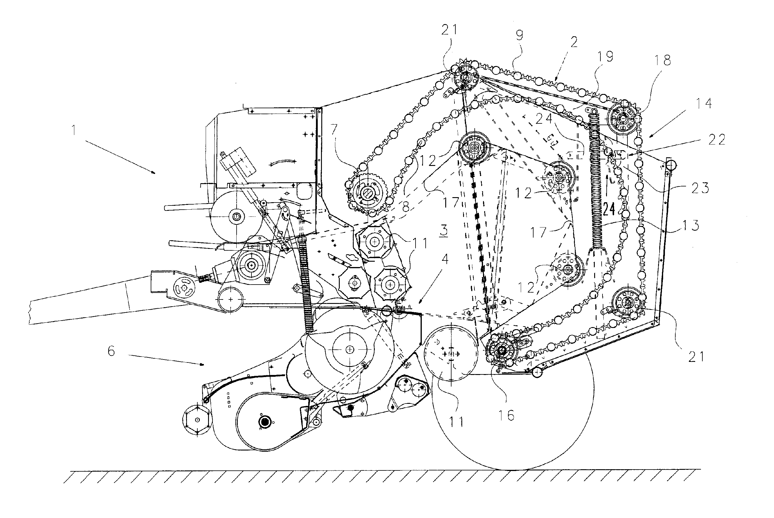
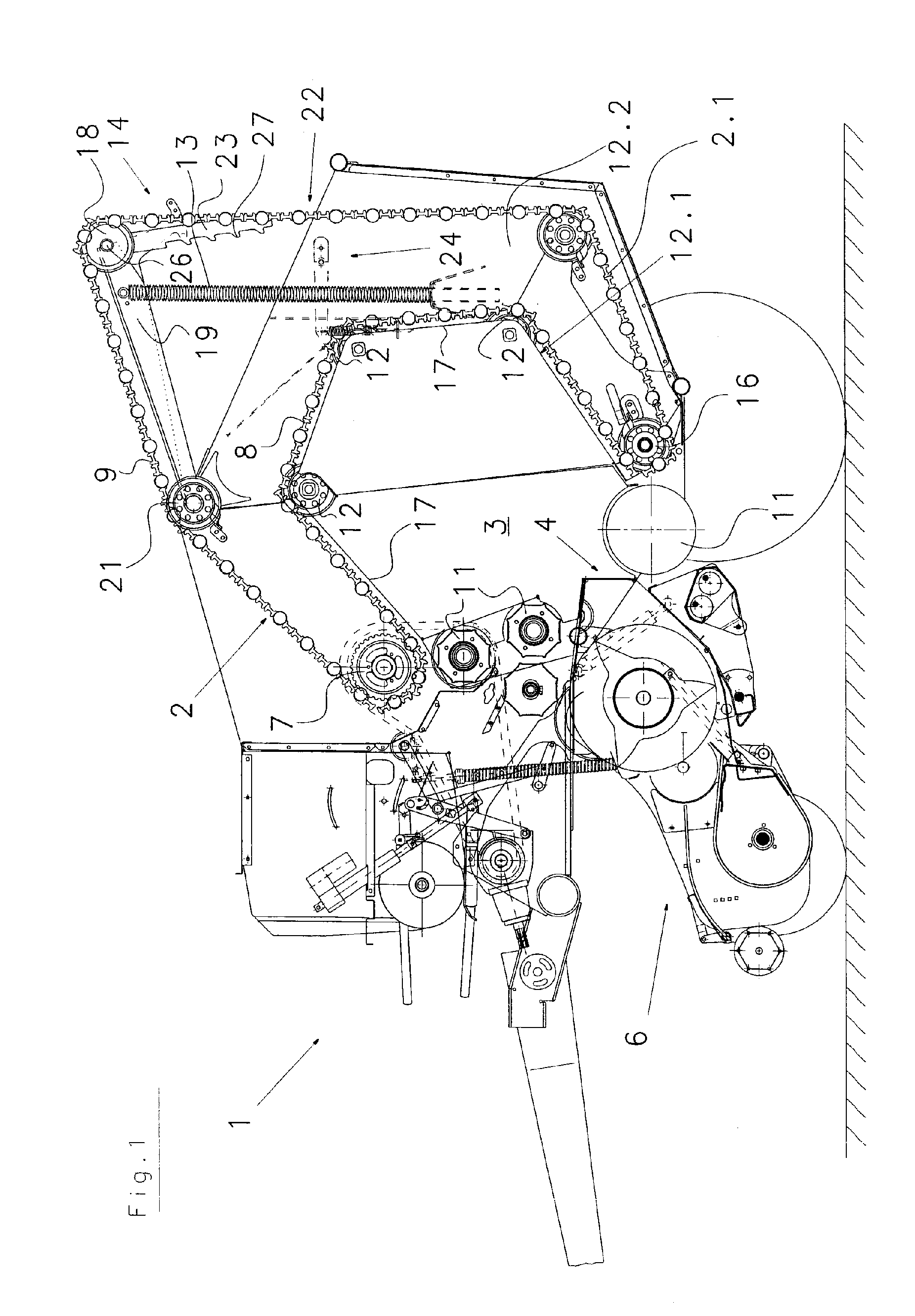
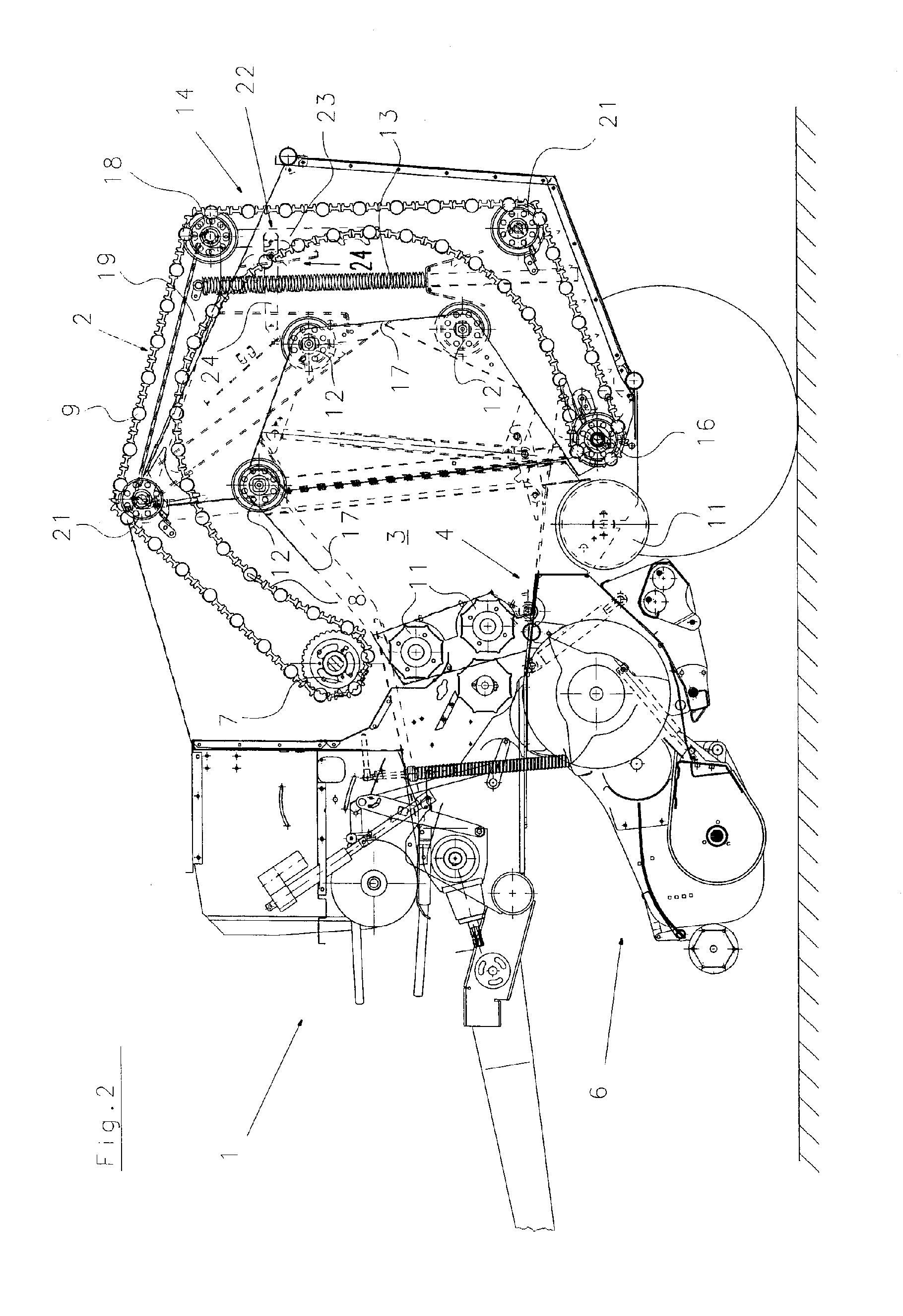
[0020] The drawings show in a few illustrations one side of the machine with the parts provided thereat. It is understood that these parts are present or may be present also on the other machine side that is not illustrated.

[0021] The machine 1 in the illustrated embodiment is a round bale press and has a bale-forming device 2 that forms a winding chamber 3. This winding chamber 3 has an intake opening 4 through which the harvested material or crop collected by the crop collecting device 6, for example, hay and silage, is introduced into the winding chamber 3. A drive roller 7 divides the bale-forming device 2 into a load run and a return run 9. The rollers 11 (conveying elements) that are arranged on opposed sides of the opening 4 delimit the winding chamber 3.

[0022] In addition, a first stationary deflection device in the form of deflection rollers 16 as well as a second deflection device in the form of deflection rollers 7 are provided, wherein the deflection rollers 7 are the ...


PUM


Abstract

A machine for collecting and pressing a crop to roll-shaped bales has a crop collecting device and a bale-forming device with a winding chamber arranged downstream of the crop collecting device. The bale-forming device is guided about first and second stationary deflection devices. Guides are positioned between the first and second stationary deflection guides. During a first bale-forming phase, the bale-forming device travels along a spatially determined movement path on the guides. During a subsequent bale-forming phase, the bale-forming device is transferred to additional movement paths that are independent of the guides and are determined by the diameter of the bale. The maximum bale diameter is selectable by moveable control devices. After the bale reaches the selected maximum diameter, the bale-forming device initiates a compression phase and exerts a compression force on the bale from the exterior to the interior of the bale.

Description

BACKGROUND OF THE INVENTION [0001] The invention relates to a machine for collecting and pressing an agricultural harvest or crop, for example, grass, hay, straw or the like, to roll-shaped bales. The machine comprises a winding chamber that can be opened, wherein the winding chamber has a bale-forming device arranged downstream of the crop collecting device and guided across at least a first and a second stationary deflection devices. During a bale-forming phase, the bale-forming device travels within the winding chamber along a spatially determined movement path on guides. For compressing the bale to be formed after reaching a maximum bale diameter, the bale-forming device exerts on the bale a compression force in a direction from the exterior to the interior of the bale. [0002] In customary configurations, machines of the aforementioned kind for collecting and pressing an agricultural harvest or crop are designed as round balers having a fixed chamber configuration; they have a b...

Claims


Application Information

Patent Timeline
IPC IPC(8): A01F15/07A01F15/08
CPCA01F15/0833A01F2015/0795A01F2015/077
Inventor KRONE, BERNARDMARTENSEN, KLAUS
Owner MASCHFAB BERNARD KRONE GMBH
Why Eureka
Try Eureka