Leadless lower temperature co-crystal phase transition metal heat conductive device

Inactive Publication Date: 2005-11-17
AMPEC TECH
View PDF7 Cites 11 Cited by
  • Summary
  • Abstract
  • Description
  • Claims
  • Application Information

AI Technical Summary

Benefits of technology

[0003] Accordingly, the primary object of the present invention is to provide a leadless lower temperature co-crystal phase transition metal heat conductive device which comprises two metal substrates made from tin, indium, bismuth and a little other elements; a metal heat conductive sheet installed between the two metal substrates, where the metal substrates having the effect of increasing heat dissipating ability of the metal heat conductive sheet; a heat dissipation device install

Problems solved by technology

However, most of the heat conductive glue A or film contain with lead which has lower heat conductivity.
Moreover, the heat conductive glue A or film cannot be used rep

Method used


Image

  • Leadless lower temperature co-crystal phase transition metal heat conductive device
  • Leadless lower temperature co-crystal phase transition metal heat conductive device
  • Leadless lower temperature co-crystal phase transition metal heat conductive device

Examples


Example

[0010] In order that those skilled in the art can further understand the present invention, a description will be described in the following in details. However, these descriptions and the appended drawings are only used to cause those skilled in the art to understand the objects, features, and characteristics of the present invention, but not to be used to confine the scope and spirit of the present invention defined in the appended claims.

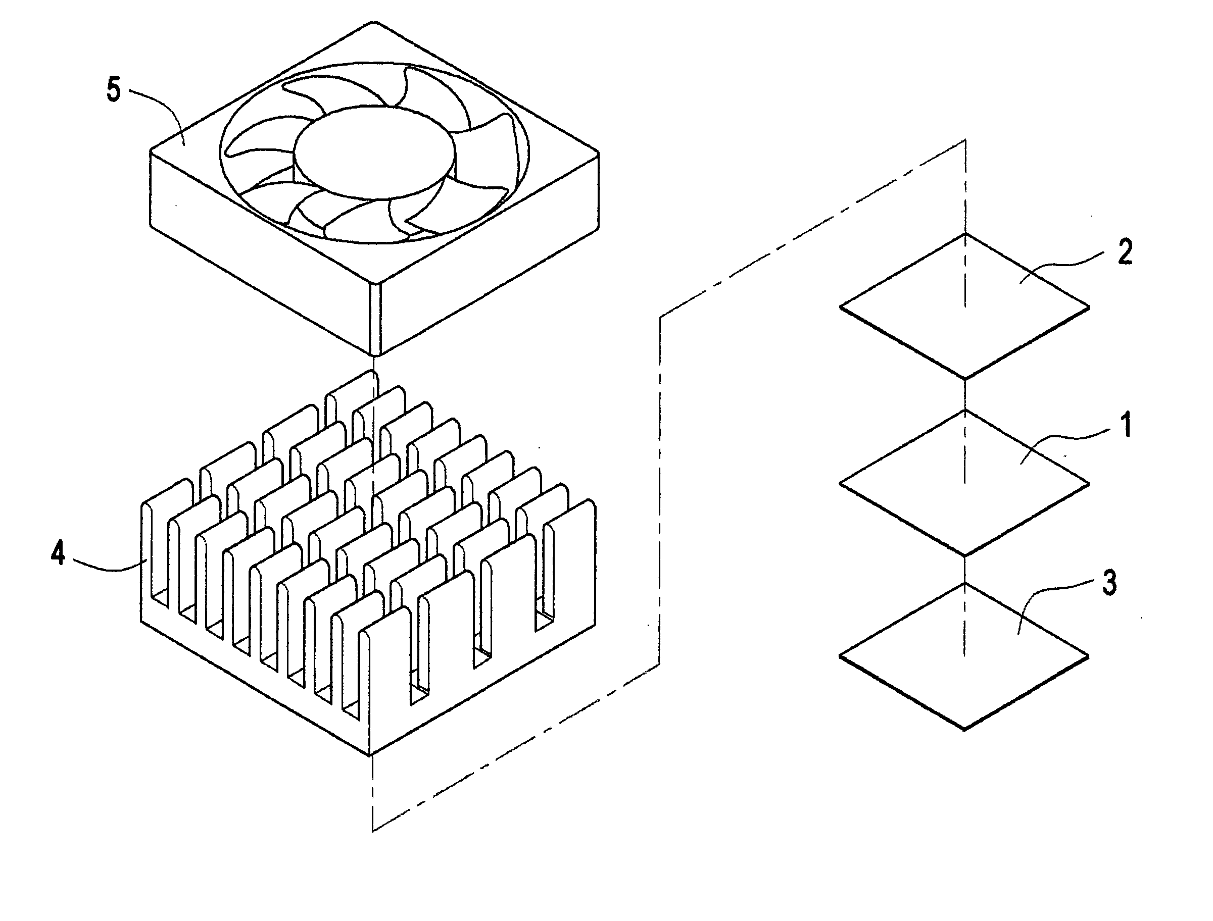
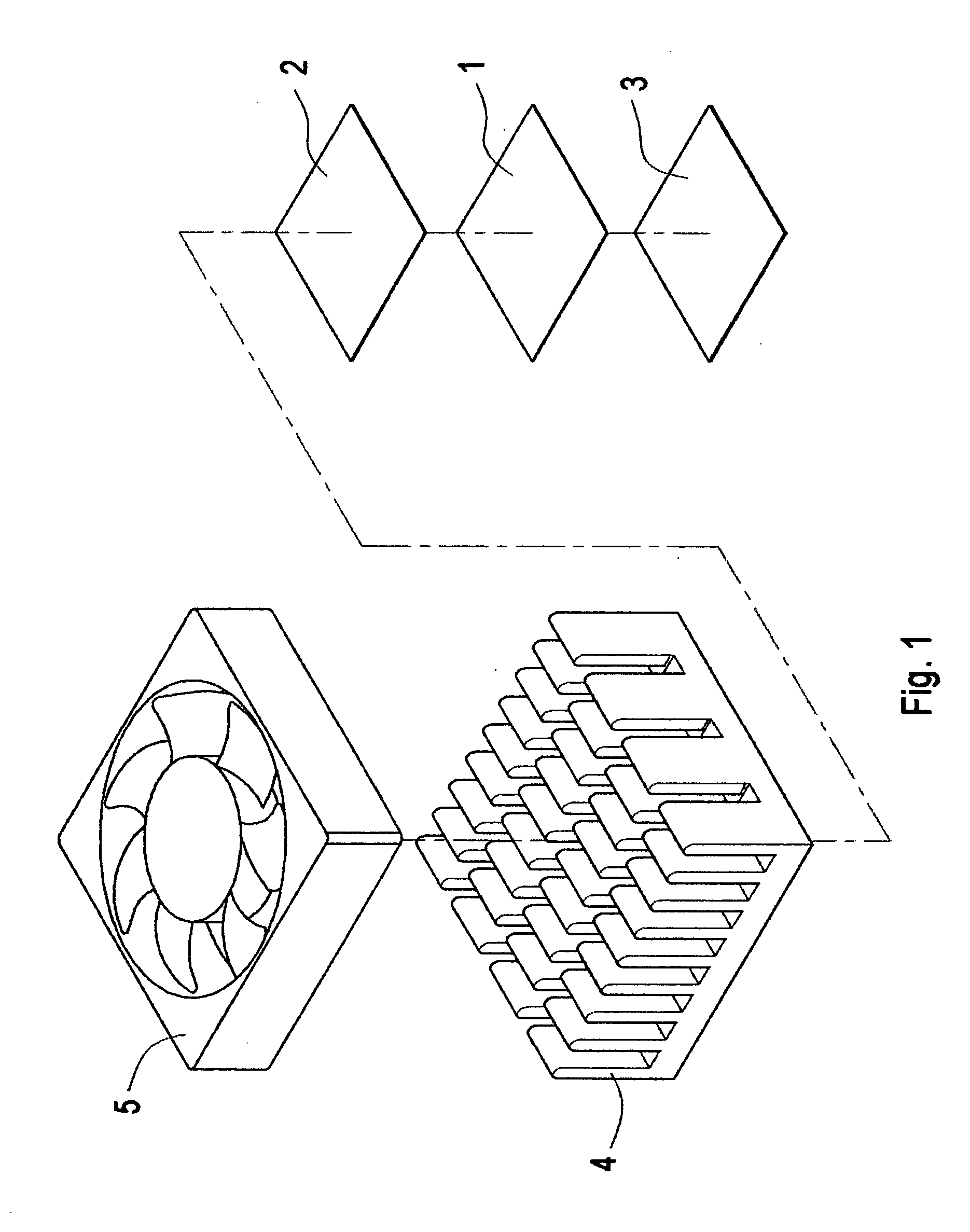
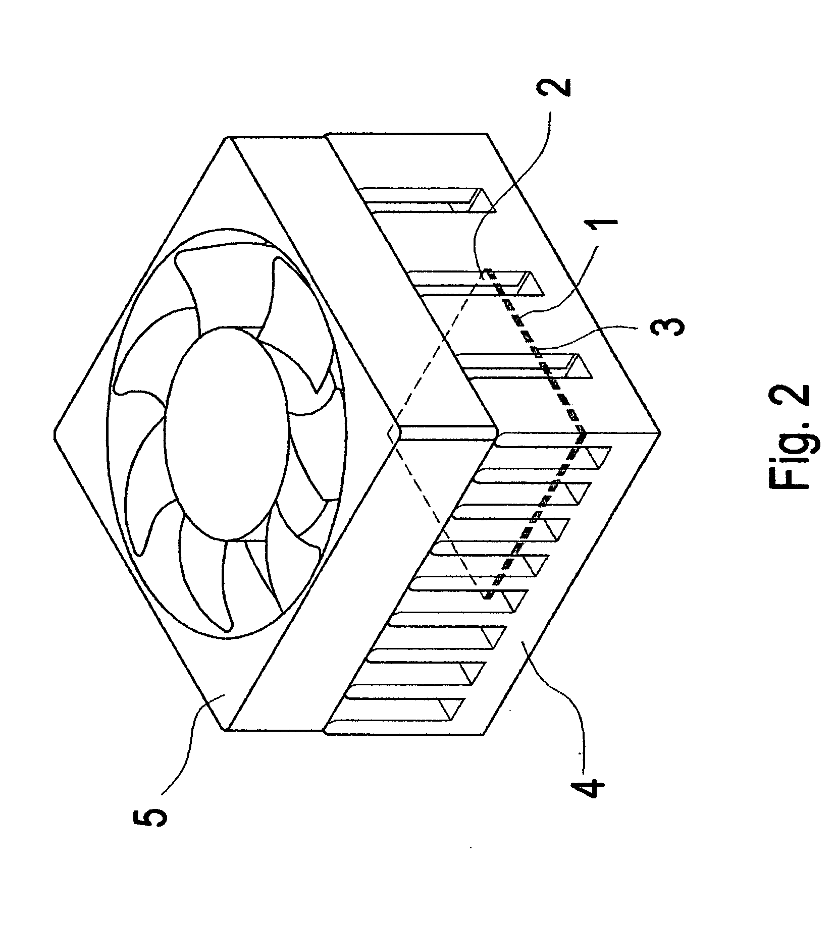
[0011] With reference to FIGS. 1, 2 and 3, the leadless lower temperature co-crystal phase transition metal heat conductive sheet. The present invention mainly comprises the following elements.

[0012] Two metal substrates 2 and 3 are made from tin, indium, bismuth and a little other elements.

[0013] A metal heat conductive sheet 1 is installed between the two metal substrates 2 and 3, where the metal substrates 2 and 3 have the effect of increasing heat dissipating ability of the metal heat conductive sheet 1.

[0014] A heat dissipation device 4 ...


PUM


Abstract

A leadless lower temperature co-crystal phase transition metal heat conductive device comprises two metal substrates made from tin, indium, bismuth and a little other elements; a metal heat conductive sheet installed between the two metal substrates, where the metal substrates having the effect of increasing heat dissipating ability of the metal heat conductive sheet; a heat dissipation device installed above a structure formed by the metal substrates and the metal heat conductive sheet so as to dissipate heat from the metal heat conductive sheet and the two metal substrates; and a fan installed above the heat dissipation device for dissipating heat from the heat dissipation device. When leadless lower temperature co-crystal phase transition metal heat conductive device is placed on a circuit board, the temperature range for co-crystal phase transition is between 50° C. to 70° C.

Description

FIELD OF THE INVENTION [0001] The present invention relates to a heat dissipation device, and particular to a leadless lower temperature co-crystal phase transition metal heat conductive device which has higher heat dissipating effect by using two metal substrates to enclose one layer of metal heat conductive sheet. BACKGROUND OF THE INVENTION [0002] With reference to FIG. 5, conventionally, heat conductive glue A or a film is coated upon a bottom of a heat dissipation device. However, most of the heat conductive glue A or film contain with lead which has lower heat conductivity. Moreover, the heat conductive glue A or film cannot be used repeatedly. Further, coating the heat conductive glue A or the film is performed manually so that the distribution of the heat conductive glue A or the film is not uniform. Thereby, if too much heat conductive glue A or film is coated, then some of the heat conductive glue A or film will be extruded out so as to pollute the environment and as a res...

Claims


Application Information

Patent Timeline
IPC IPC(8): F28F7/00H01L23/373H01L23/467
CPCH01L23/3736H01L23/467H01L2924/0002H01L2924/00
Inventor CHIU, MING-CHICHANG, HSIN-HSIANG
Owner AMPEC TECH
Why Eureka
Try Eureka