Powered manual propelling vehicle
a technology of manual propelling and propelling wheels, which is applied in the direction of propulsion by batteries/cells, electric devices, sport apparatus, etc., can solve the problem of difficulty in carrying work, and achieve the effect of preventing play
- Summary
- Abstract
- Description
- Claims
- Application Information
AI Technical Summary
Benefits of technology
Problems solved by technology
Method used
Image

Examples
first embodiment
[0071] the present invention will be described with reference to FIG. 1 to FIG. 12.
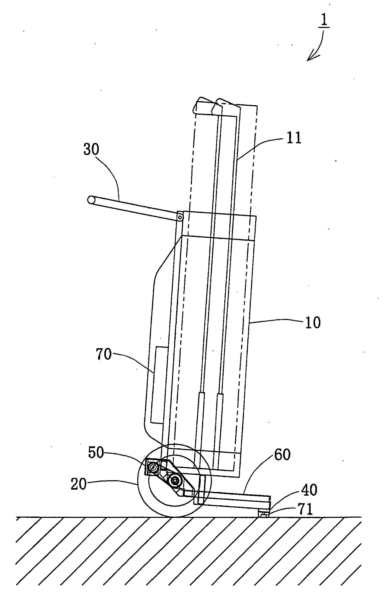
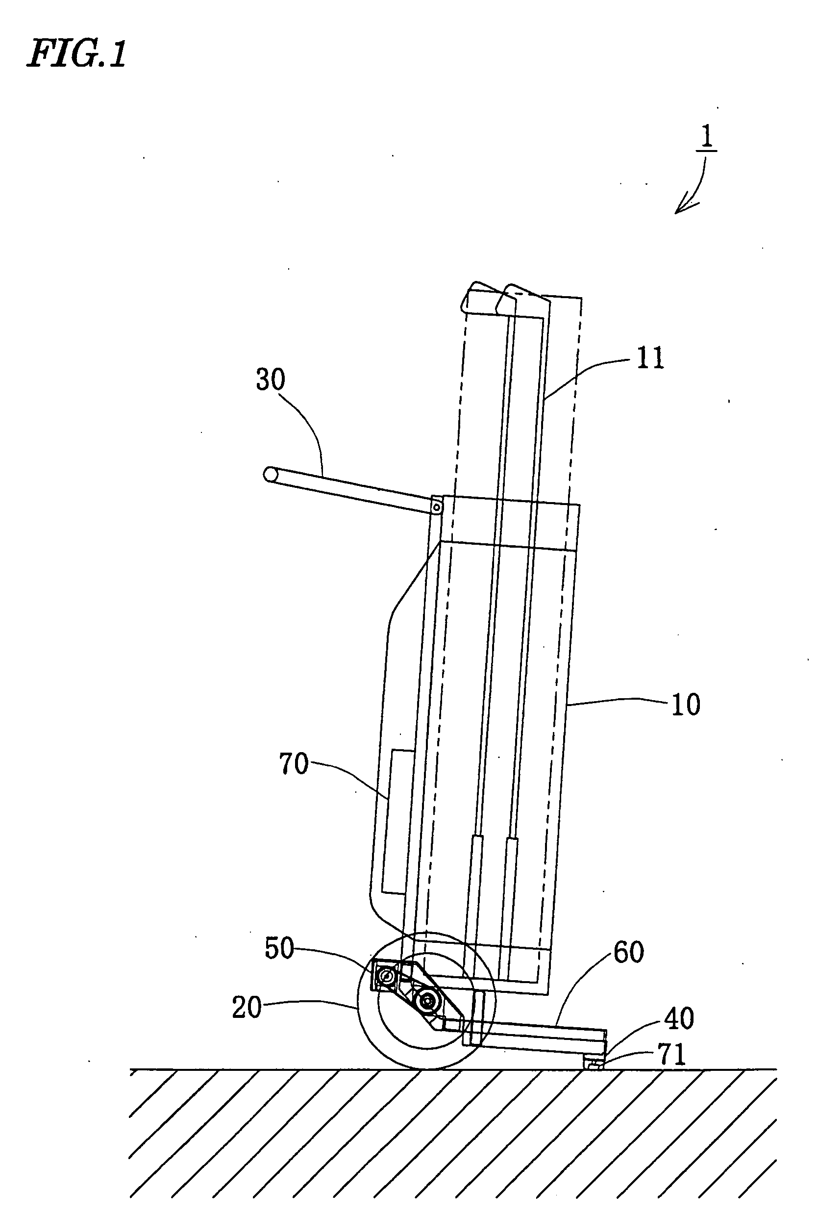
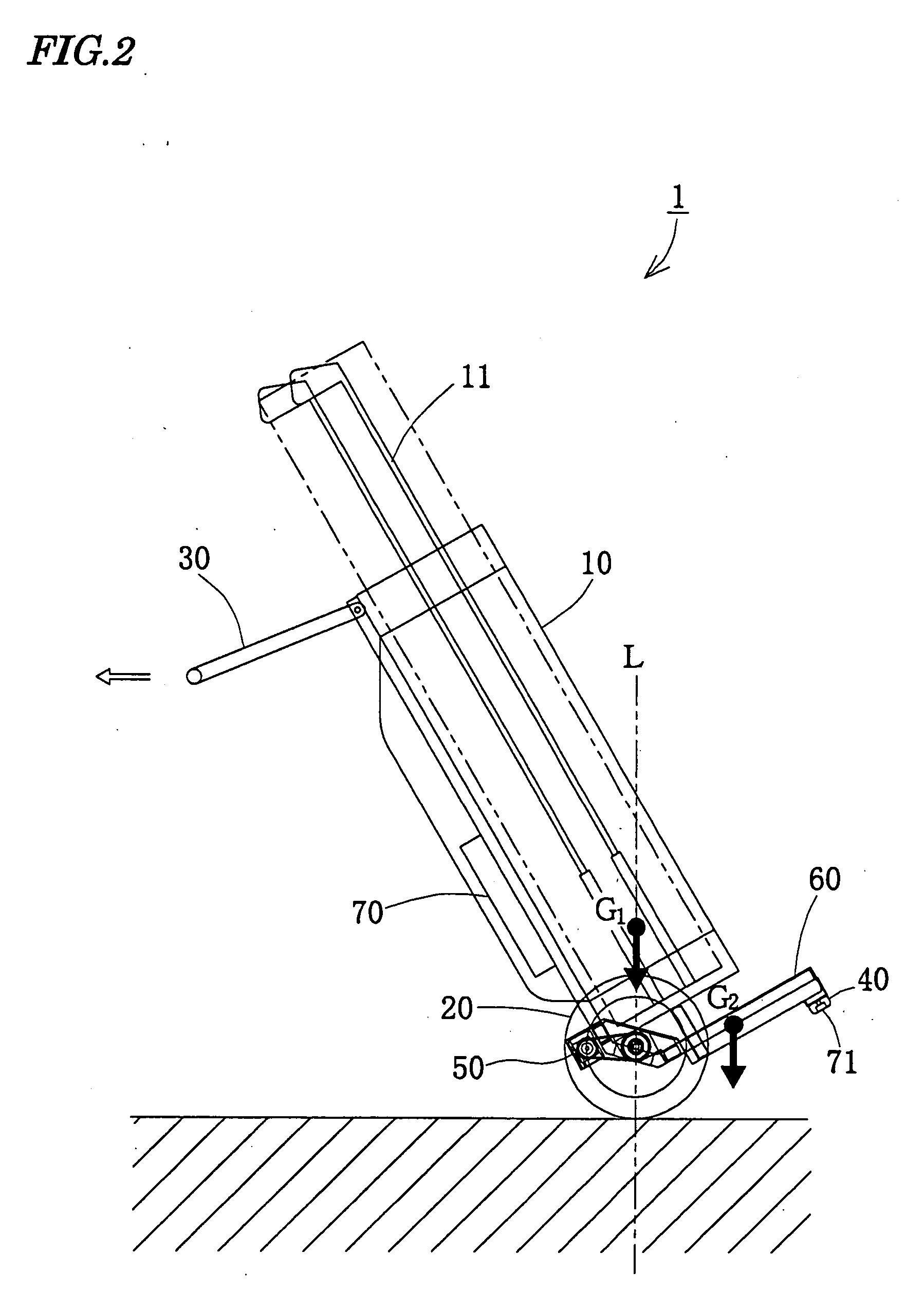
[0072] As shown in FIG. 1 and FIG. 2, a powered manual propelling vehicle 1 is a golf bag which has wheels 20 and a handle 30 fitted to a case body 10 which has a size required for containing a golf equipment 11. IN a stationary state, it is stood still with a supporting portion 40, which is provided at a prescribed position, placed an the ground, and to use it, a user grips the handle 30 and tilts the vehicle 1 with the wheels 20 as fulcrums to run it. An arrow in FIG. 2 indicates a traveling direction of the powered manual propelling vehicle 1 when traveling.
[0073] The case body 10 is formed by screwing or riveting a cylindrical member of resin or cloth to an aluminum frame. The handle 30 is mounted on the case body 10 foldably or detachably.
[0074] This powered manual propelling vehicle 1 is also provided with a motor 50 for driving the wheels 20, a battery 60 as a power source for the motor 50 an...
second embodiment
[0099] Then, the present invention will be described with reference to FIG. 13 to FIG. 15.
[0100] As shown in the drawings, the powered manual propelling vehicle 1 of this embodiment has a carrier 90 to which the wheels 20, the motor 50 and the battery 60 are mounted, and the carrier 90 is attached foldably to the case body 10. FIG. 13 shows the carrier 90 in the folded state, FIG. 14 shows the carrier 90 in the opened state when the vehicle is stopped and FIG. 15 shows a traveling state.
[0101] The carrier 90 is rotatably supported by the case body 10 and, when it is opened, it is fixed by engaging with a locking portion 91 which is disposed on a prescribed position. The carrier 90 is provided with ushing means such as a spring and can be interlocked with the handle 30, such that it can be folded or opened by operating the handle 30. The other basic configuration is the same as in the above-described embodiment.
[0102] By configuring as described above, the powered manual propelling...
third embodiment
[0104] Then, the present invention will be described with reference to FIG. 16 to FIG. 19.
[0105] The powered manual propelling vehicle 1 of this embodiment is provided with a traveling speed detecting means for detecting its traveling speed, and the control section 70 sets a target traveling speed of the vehicle 1 and an upper limit of torque of the motor 50 according to the traveling speed detected by the traveling speed detecting means, and controls the motor 50 such that the traveling speed agrees with the target traveling speed in a range that the torque of the motor 50 does not exceed its upper limit.
[0106] In this embodiment, the encoder 50a is used as the traveling speed detecting means. The traveling speed is detected by converting the speed ratio of the wheels 20 and the motor 50 and the circumferences of the wheels 20 into the rotation speeds of the motors 50. The other basic structures are the same as in the above-described embodiment.
[0107] In this embodiment, the cont...
PUM
 Abstract
Description
Claims
Application Information
 - R&D
- Intellectual Property
- Life Sciences
- Materials
- Tech Scout
- Unparalleled Data Quality
- Higher Quality Content
- 60% Fewer Hallucinations
Browse by: Latest US Patents, China's latest patents, Technical Efficacy Thesaurus, Application Domain, Technology Topic, Popular Technical Reports.
© 2025 PatSnap. All rights reserved.Legal|Privacy policy|Modern Slavery Act Transparency Statement|Sitemap|About US| Contact US: help@patsnap.com