Method for manufacturing electroacoustic transducer diaphragm

a technology of electroacoustic transducers and diaphragms, which is applied in the direction of diaphragm construction, applications, other domestic articles, etc., can solve the problems of paper diaphragm, difficult to manufacture, and difficult to manufactur

Inactive Publication Date: 2005-11-17
PIONEER CORP +1
View PDF3 Cites 26 Cited by
  • Summary
  • Abstract
  • Description
  • Claims
  • Application Information

AI Technical Summary

Problems solved by technology

However, each of the materials has its own inherent characteristics, which result in advantages and disadvantages in terms of properties required of a diaphragm.
Therefore, in actual practice, causing a diaphragm formed from a single material to exhibit a number of properties required of a diaphragm in good balance encounters significant difficulty.
On the other hand, the paper diaphragm has disadvantages of involving difficulty in ensuring waterproofness, and difficulty in increasing elastic modulus for the purpose of ensuring a large maximum power input.
On the other hand, such a diaphragm has disadvantages of having a high density and a small internal loss (although some resins have large internal losses) Therefore, such a diaphragm is not necessarily o...

Method used


Image

  • Method for manufacturing electroacoustic transducer diaphragm
  • Method for manufacturing electroacoustic transducer diaphragm
  • Method for manufacturing electroacoustic transducer diaphragm

Examples


Embodiment Construction

[0034] Hereinafter, a method for manufacturing an electroacoustic transducer diaphragm according to a preferred embodiment of the invention will be described in detail by reference to the drawings.

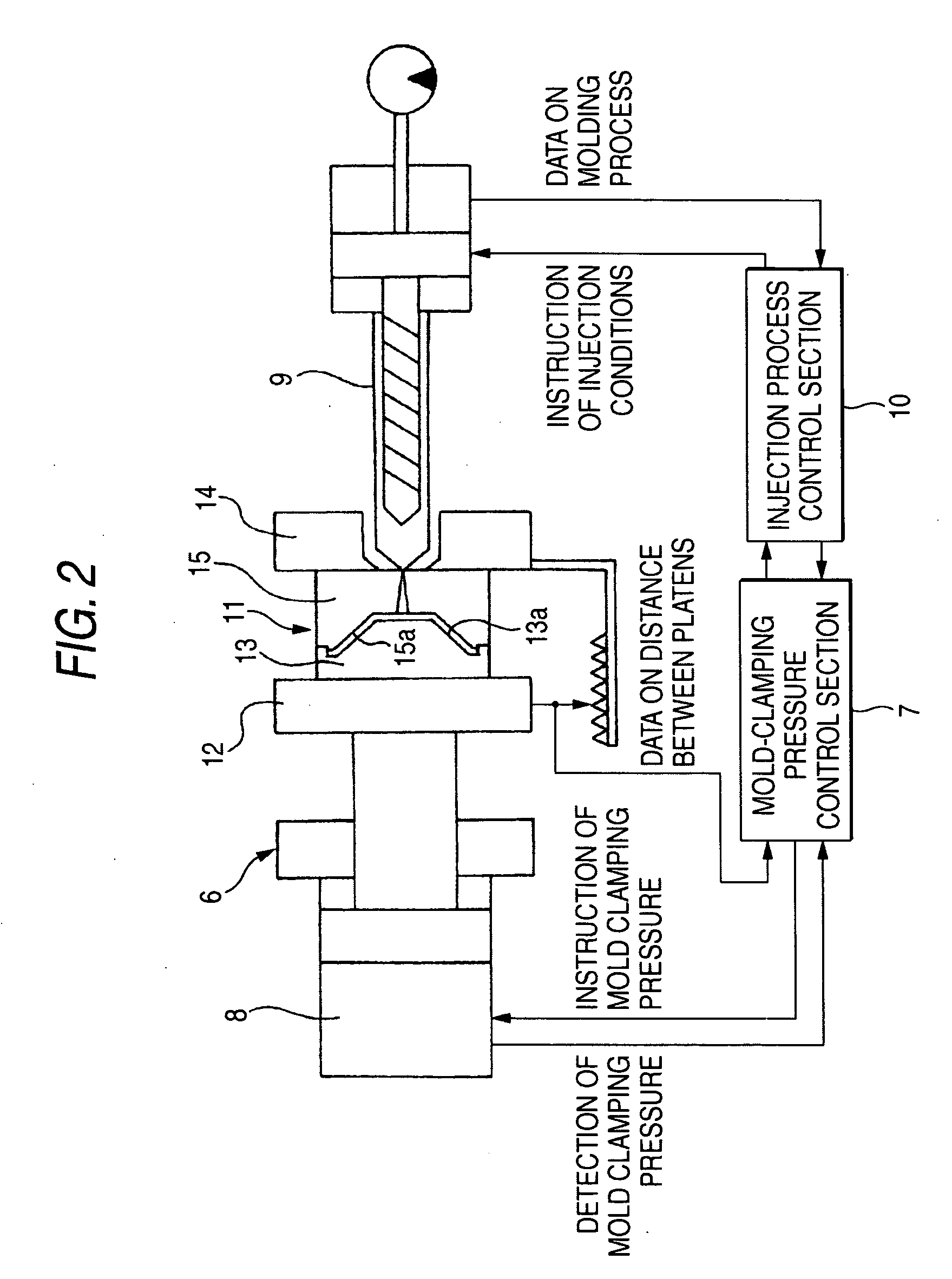
[0035]FIG. 2 is a block diagram showing a schematic configuration of an injection molding machine for use in an embodiment of a method for manufacturing an electroacoustic transducer diaphragm according to the invention.

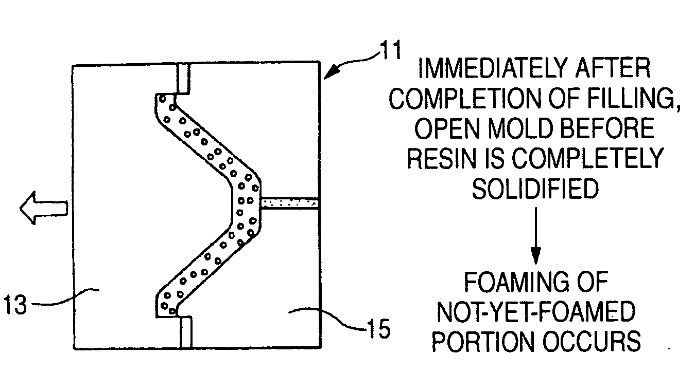
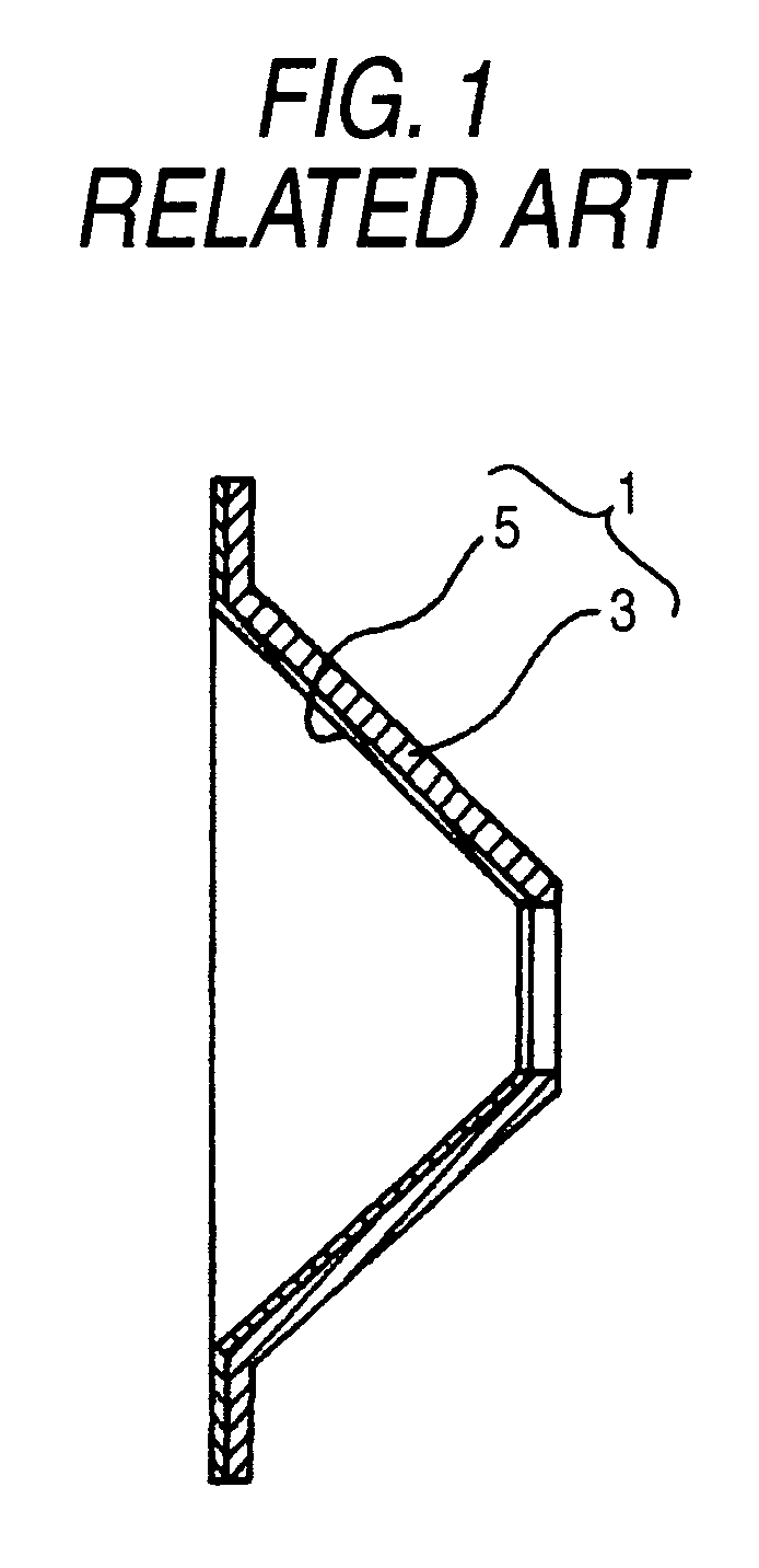
[0036] An injection mold 11 of an injection molding machine 6 shown in FIG. 2 is a mold for manufacturing an electroacoustic transducer diaphragm 1 shown in FIG. 1. The injection mold 11 includes a male mold 13 having a conical protruding section 13a along the contour of the surface of the electroacoustic transducer diaphragm 1, and a female mold 15 having a conical recessed section 15a corresponding to the conical protruding section 13a.

[0037] In the present embodiment, the male mold 13 is actuated as a movable mold while being held by a movable platen 12. The female mo...


PUM


Abstract

A method for manufacturing an electroacoustic transducer diaphragm of a multilayered structure which includes a first diaphragm layer made from a synthetic resin material and molded into a predetermined shape through injection molding, and a second diaphragm layer laminated in close contact with the first diaphragm layer and made from a material differing from that of the first diaphragm layer, the method includes inserting the second diaphragm layer into a mold for injection molding, the second diaphragm layer being made of not-yet-molded woven fabric or woven fabric molded previously into a predetermined shape of a diaphragm, and injecting the synthetic resin material which is to be molded into the first diaphragm layer into the mold for injection molding, thereby forming the first diaphragm layer integrally with the second diaphragm layer.

Description

BACKGROUND OF THE INVENTION [0001] 1. Field of the Invention [0002] The present invention relates to a method for manufacturing an electroacoustic transducer diaphragm, and particularly to a method for manufacturing an electroacoustic transducer diaphragm of a multilayered structure including a first diaphragm layer made from a synthetic resin and molded into a predetermined shape through injection molding, and a second diaphragm layer (a skin layer) laminated on the first diaphragm layer in close contact therewith and made from a material different from that of the first diaphragm layer. [0003] 2. Description of the Related Art [0004] Properties required of a diaphragm for an electroacoustic transducer, such as a speaker or a microphone, include a large specific modulus (E / ρ), a large specific flexural rigidity (E / ρ3), and an appropriate internal loss, as well as high resistance to mechanical fatigue and weathering. In addition, in recent years, waterproofness has become an essenti...

Claims


Application Information

Patent Timeline
IPC IPC(8): B29B13/00B29C31/00B29C45/14B29C37/00B29C45/56H04R7/02H04R7/12H04R25/00H04R31/00
CPCB29C37/0032B29C44/1233B29C45/1418B29C45/14467H04R31/003B29C2037/0042B29C2045/14532B29K2713/00B29L2031/755B29C45/561
Inventor TAKAYAMA, KOJISATO, MASATOSHIHAYASAKA, SHINICHIKOBAYASHI, HIROYUKI
Owner PIONEER CORP
Why Eureka
Try Eureka