

Vibration-damping device for vehicles and method of manufacturing the same
a technology for vibration-damping devices and vehicles, which is applied to shock absorbers, machine supports, other domestic objects, etc., can solve the problems that the prior technology could not achieve, and achieve the effect of stabilizing the impact of independent mass members and improving the vibration-damping
- Summary
- Abstract
- Description
- Claims
- Application Information
AI Technical Summary
Benefits of technology
Problems solved by technology
Method used
Image

Examples
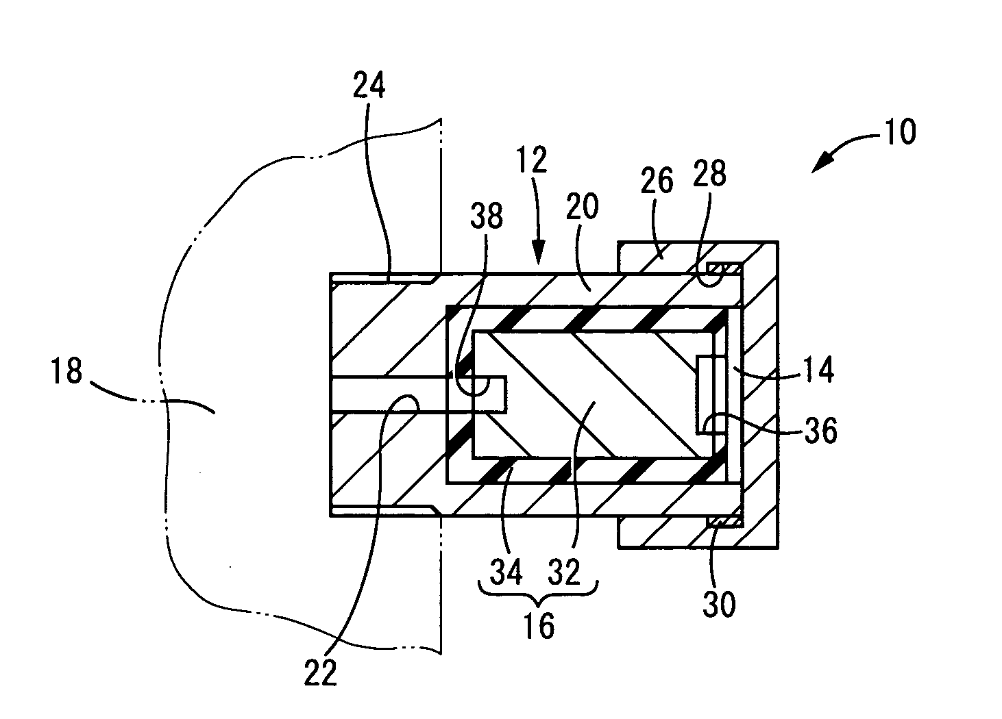
first embodiment
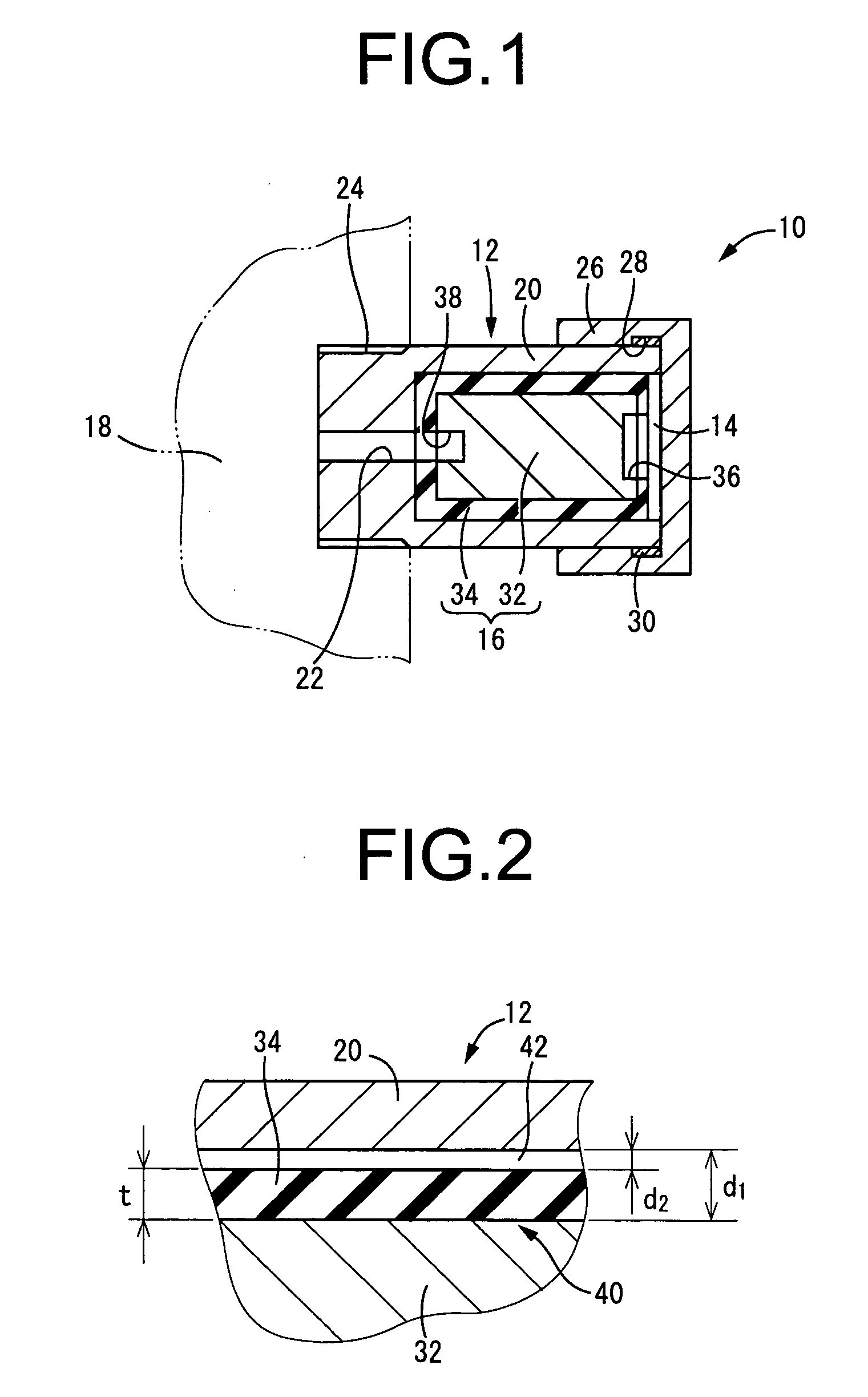
[0080] Further, a thin striking rubber layer 34 covers essentially the entirety of the outer peripheral surface of the metallic mass 32. The striking rubber layer 34 has a thickness dimension (t) that is sustained as in the first embodiment, described above. In a state where the metallic mass 32 is disposed coaxially with the housing 12, the striking rubber layer 34 faces the housing 12 so that over the entire periphery there is a radial-direction distance d2 between the facing surfaces of the outer peripheral surface of the striking rubber layer 34 and the inner peripheral surface of the housing 12. With this arrangement, a small gap 42 with a small dimension (d2) is formed between the radially opposing surfaces, i.e., the external peripheral surface of the striking rubber layer 4 and the inner peripheral surface of the housing (See FIG. 13).
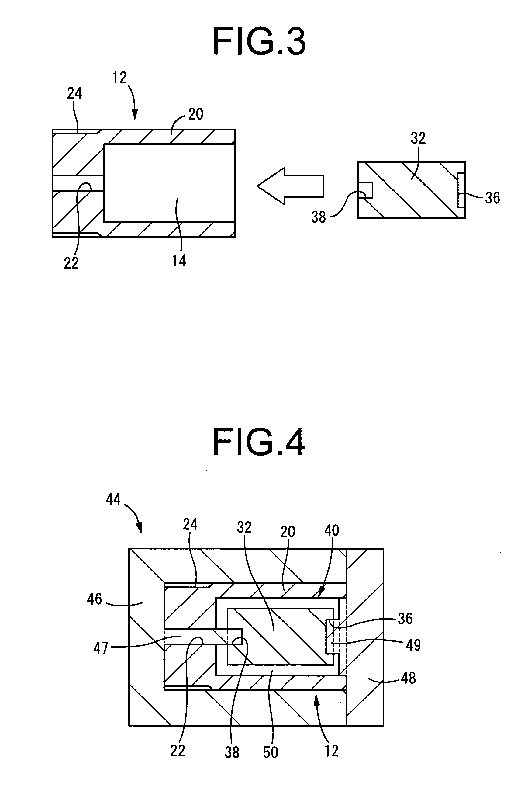
[0081] In the present embodiment, a runner 82 for the injection of a rubber material 34′ is formed at at least one of the axial ends of the me...
second embodiment
[0091] In the second embodiment, the rubber material 34′ for the striking rubber layer 34 is filled into the mold cavity 50 through the runner 82 for injection fabricated in the metallic mass 32. However, instead the rubber material 34′ may be filled into the mold cavity 50 through a separate runner, or the like, fabricated in the fabrication mold 84 that opens directly into the space between the radially opposing surfaces of the metallic mass 32 and the housing 12.
[0092] Furthermore, in the second embodiment, the rubber elastic body 66 and the striking rubber layer 34 were integrated. However, the fabrication of the striking rubber layer 34 may be performed in a separate process from the fabrication of the rubber elastic body 66. Specifically, after the vulcanization molding of the rubber elastic body 66, the inner cylinder 62 and outer cylinder 64, and housing 12 may be placed on a fabrication mold that has been prepared separately from the integrally vulcanized product of the rub...
PUM
| Property | Measurement | Unit |
|---|---|---|
| resonant frequency | aaaaa | aaaaa |
| frequency | aaaaa | aaaaa |
| distance d1 | aaaaa | aaaaa |
Abstract
Description
Claims
Application Information