Press-fitted film inserting means of press-fotted paper manfacturing equipment

a technology of press-fotted paper and inserting means, which is applied in the direction of paper/cardboard articles, box making operations, paper/cardboard containers, etc., can solve the problem of contact-bonding film not being smoothly inserted between paper pieces

Inactive Publication Date: 2005-11-17
MATSUSHITA SEIKO CO LTD
View PDF4 Cites 9 Cited by
  • Summary
  • Abstract
  • Description
  • Claims
  • Application Information

AI Technical Summary

Benefits of technology

[0032] According to the above structure, when the lower paper piece of the folded paper is transferred to the intersection in the condition that the periphery of the lower paper piece is curved upward, the lower paper piece can easily slide into the wide open space below the periphery of the support plate which is curved upward by the support plate raising means. Thus, the lower paper piece can be pushed down by the downward movement of the support plate and subsequently the support plate and the contact-bonding film can be normally inserted between the paper pieces utilizing the wedge shape of the slope.

Problems solved by technology

In this case, the space between the paper pieces is not sufficiently opened when the lower paper piece is pushed down by the downward movement of the support plate as described above, and thus the contact-bonding film is not smoothly inserted between the paper pieces in the manner as described above.

Method used


Image

  • Press-fitted film inserting means of press-fotted paper manfacturing equipment
  • Press-fitted film inserting means of press-fotted paper manfacturing equipment
  • Press-fitted film inserting means of press-fotted paper manfacturing equipment

Examples


first embodiment

(4) Contact-Bonding Film Insertion Means of a First Embodiment for Solving the Above Problem

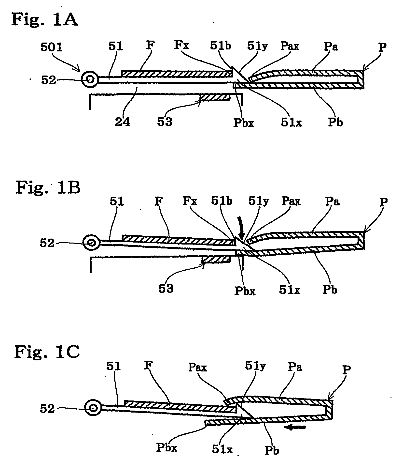
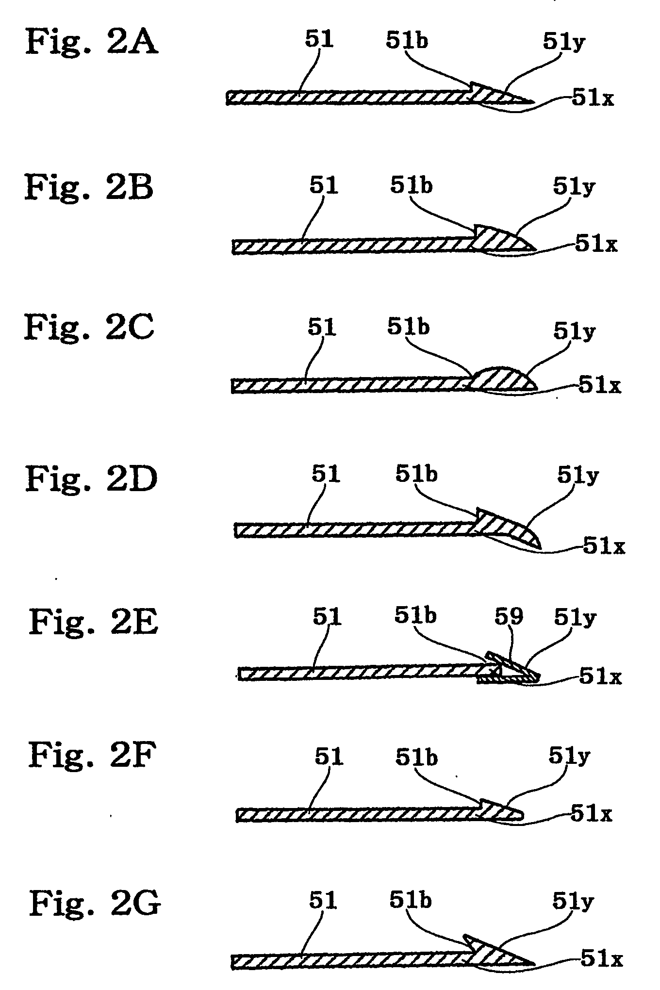
[0062] In contact-bonding film insertion means 501 in the first embodiment according to the present invention as illustrated in FIGS. 1A through 1C, a slope 51y is provided in the periphery 51x of the support plate 51 on the side to be inserted between the paper pieces Pa and Pb. The slope 51y has a linear cross section and is downward-inclined toward its tip to form substantially an acute angle at the tip, and extends above the periphery 51x of the support plate 51 and further above the periphery Fx of the contact-bonding film F placed on the support plate 51, which periphery Fx is on the side to be inserted between the paper pieces Pa and Pb, whereby the slope 51y has an arrow-shaped cross section. A step-shaped contact portion 51b for guiding the periphery Fx of the contact-bonding film F on the side to be inserted between the paper pieces Pa and Pb is also provided in the periphery 51x ad...

second embodiment

(6) Contact-Bonding Film Insertion Means of a Second Embodiment for Solving the Second Problem

[0069] In contact-bonding film insertion means 502 in the second embodiment, the periphery 51x which includes the slope 51y having a shape and a structure shown in FIGS. 1A through 1C is curved upward with respect to the main body of the support plate 51 as illustrated in FIGS. 3A through 3C, thereby providing a wide open space below the support plate 51.

[0070] More specifically, in the contact-bonding film insertion means 502 which includes the support plate 51 having the above structure, the lower paper piece Pb of the paper P which is folded and transferred to the intersection 24 easily slides into the wide open space below the periphery 51x of the support plate which is curved upward, even if the periphery Pbx of the lower paper piece Pb is curved upward as illustrated in FIG. 3A. In the subsequent step, the periphery Pbx of the lower paper piece Pb is normally pushed down by the downw...

third embodiment

(7) Contact-Bonding Film Insertion Means of a Third Embodiment for Solving the Second Problem

[0072] As illustrated in FIGS. 5A through 5D, contact-bonding film insertion means 503 in the third embodiment has a structure similar to that of the contact-bonding film insertion means 501 including the support plate 51 whose periphery 51x has the slope 51y having the shape and structure shown in FIGS. 1A through 1C. The periphery 51x of the support plate 51 in which the slope 51y is formed is temporarily raised by support plate raising means 65 before the lower paper piece Pb of the paper P transferred to the intersection 24 reaches the support plate 51, thereby providing a wide open space below the support plate 51 at the time when the space is required.

[0073] More specifically, in the contact-bonding film insertion means 503 using the support plate 51 and having the above structure, the folded paper P is transferred to the intersection 24 as illustrated in FIG. 5A. Then, a push rod 67 ...


PUM

PropertyMeasurementUnit
transparentaaaaaaaaaa
sizeaaaaaaaaaa
acute angleaaaaaaaaaa

Abstract

In contact-bonding film insertion means included in contact-bonded paper manufacturing apparatus which produces releasable and expandable contact-bonded paper such as postcards (Q) by inserting a contact-bonding film (F) carried on a vertically movable support plate (51) between opposed paper pieces (Pa, Pb) of folded cut paper (P) by paper pushing means (60), the cut paper (P) having been transferred by paper transfer means (20) and folded by paper folding means (30), and subsequently by extracting the support plate (51) from the paper piece (Pa, Pb) by support plate extracting means (55) to supply the paper (P) into which only the contact-bonding film F is inserted to paper contact-bonding means (70) and paper cutting means (80), a slope (51y) which is downward-inclined toward its tip to form substantially an acute angle at the tip is provided on a periphery (51x) of the support plate (51) included in the contact-bonding film insertion means, the periphery (51x) which includes the slope (51y) having a shape being preferably curved upward with respect to the main body of the support plate (51). This structure allows smooth insertion of the contact-bonding film (F) between the paper piece (Pa, Pb) without occurrence of jamming or other problem even if the paper (P) is extremely curled to have concave and convex deformations on its surface through printing or other process.

Description

TECHNICAL FIELD [0001] The present invention relates to contact-bonded paper manufacturing apparatus which uses cut paper for manufacturing contact-bonded paper available for the production of direct mails, postcards, double postcards, sealed letters and so forth. More specifically, the invention relates to contact-bonding film insertion means included in contact-bonded paper manufacturing apparatus for manufacturing contact-bonded paper from cut paper which is folded into multiple layers and releasably contact-bonded with a contact-bonding film interposed between the layers, whereby a large volume of information can be concealed inside the paper in spite of ordinary appearances as direct mails, postcards, double postcards, sealed letters and the like. BACKGROUND ART [0002] Recently, contact-bonded paper has been used for increasing numbers of postal matters such as postcards so as to transmit a large quantity of information. The contact-bonded paper is manufactured by: folding pape...

Claims


Application Information

Patent Timeline
Patent Type & Authority Applications(United States)
IPC IPC(8): B31B50/36B42D15/02
CPCB42D15/02Y10T156/1741Y10T156/1343
Inventor KIMURA, YOSHIKAZUTSUCHIYA, MASATO
Owner MATSUSHITA SEIKO CO LTD
Why Eureka
Try Eureka