Clean room easy to disassemble and assemble

A clean room and load-bearing column technology, applied in the field of clean room, can solve the problems of complex structure of clean room, occupation of space, increased cost of disassembly and assembly, etc., and achieve the effect of fast construction and disassembly, easy disassembly and assembly, and saving construction period

Active Publication Date: 2015-03-25
JIANGSU SUZHOU PURIFICATION TECH
View PDF7 Cites 6 Cited by
  • Summary
  • Abstract
  • Description
  • Claims
  • Application Information

AI Technical Summary

Problems solved by technology

However, the existing clean room usually needs to use the existing building body to support its own weight, which often requires the clean room to be fixed on site. The fixed clean room structure is very complicated, and the cost of disassembly and assembly is relatively increased. The clean room needs to occupy a limited space, which is not suitable for some small hospitals, small and medium-sized processing enterprises, places where the field work is densely populated, and on-site rescue.

Method used


Image

  • Clean room easy to disassemble and assemble
  • Clean room easy to disassemble and assemble
  • Clean room easy to disassemble and assemble

Examples


Embodiment 1

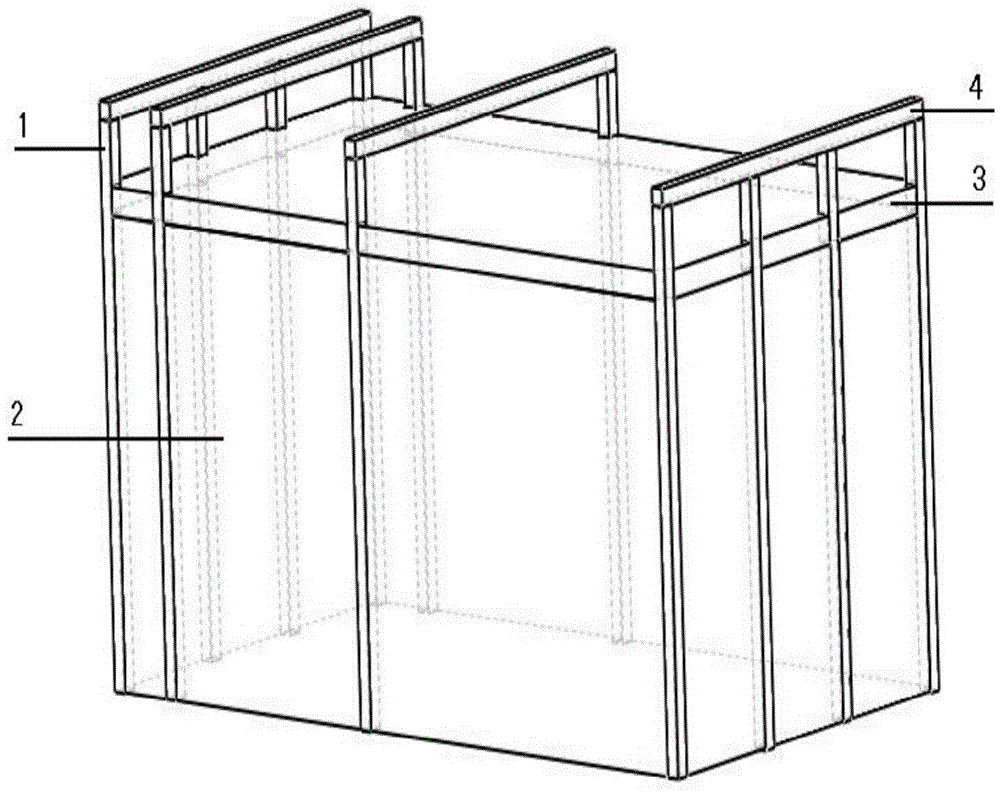
[0026] as attached figure 1 As shown, the height of the load-bearing column 1 is higher than the enclosure plate 2, and the top of the through hole of each load-bearing column 1 is clamped with a connecting groove, and a beam is arranged along the top of the load-bearing column 1 through the connecting groove. 4. The crossbeam 4 is arranged vertically to the load-bearing column 1, and the clean room is erected on the crossbeam 4 with water pipes and air pipes.

[0027] The width of the enclosure plate 2 between the two adjacent load-bearing columns 1 is 1 meter. The enclosure 2 is made of glass. The outer wall of the load-bearing column 1 is provided with a limit groove, and the limit groove is matched with the enclosure plate 2 for clamping the enclosure plate 2 . The load-bearing column 1 is made of aluminum alloy, and the bottom surface area of ​​the load-bearing column 1 is 25cm 2 . The bottom plate is the bottom surface of a plastic plate body. The beam 4 is provided...

Embodiment 2

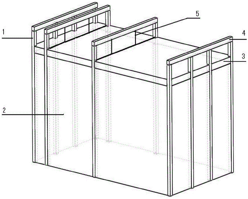
[0029] as attached figure 2 , the height of the load-bearing column 1 is higher than the enclosure plate 2, and the top of the through hole of each load-bearing column 1 is clamped with a connecting groove, and a crossbeam 4 is arranged along the top of the load-bearing column 1 through the connecting groove, The crossbeam 4 is vertically arranged with the load-bearing column 1, and the clean room is erected on the crossbeam 4 with a water pipe and an air pipe; It plays the role of hanging the connectors arranged between the splicing units of the top plate.

[0030] The width of the enclosure plate 2 between the two adjacent load-bearing columns 1 is 3 meters. The enclosure 2 is made of glass. The outer wall of the load-bearing column 1 is provided with a limit groove, and the limit groove is matched with the enclosure plate 2 for clamping the enclosure plate 2 . The load-bearing column 1 is made of aluminum alloy, and the bottom surface area of ​​the load-bearing column 1...

Embodiment 3

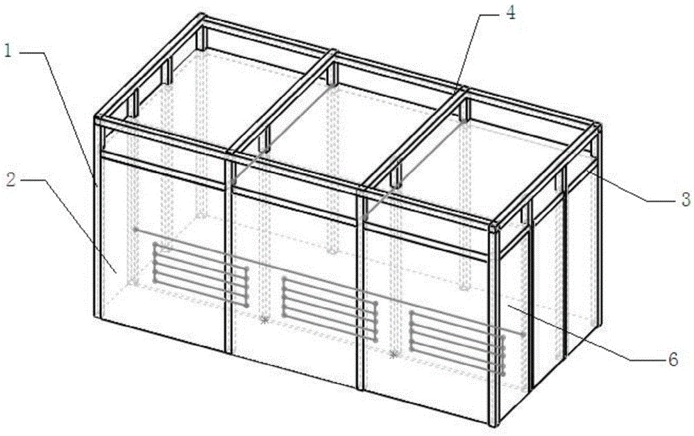
[0032] as attached Figure 3a , 3b , 3c, in the clean room, a ventilating partition is built with spaced enclosures 2 and load-bearing columns 1, through the ventilating partition, the side wall, between the side wall and the ventilating partition The top plate and the bottom plate in between form a closed ventilation interlayer 6, the lower part of the ventilation partition is provided with ventilation holes, matching with the ventilation holes, shutters are arranged at the ventilation holes, and the air flow is from the shutters through the clean The room enters the ventilation interlayer 6 and flows out from the air outlet on the top plate of the ventilation interlayer 6 .


PUM


Abstract

The invention provides a clean room easy to disassemble and assemble. The clean room easy to disassemble and assemble comprises side walls, a top plate and a bottom plate, wherein each side wall comprises a plurality of load-bearing columns arranged at intervals and guard plates located between every two adjacent load-bearing columns, a plurality of through holes are formed in each load-bearing column from top to bottom, the bottom ends of the through holes are connected to connecting bases in an inserted mode, the connecting bases are fixedly arranged under the ground surface, the bottom ends of the load-bearing columns are fixed to the connecting bases through connecting pieces, two-way connecting clamping grooves are transversely formed along the top ends of the guard plates, each two-way connecting clamping groove comprises a first clamping groove body and a second clamping groove body which are connected at a 90-degree angle in two directions, and the first clamping groove bodies are connected with the top ends of the guard plates; the top plate is of a plate-like structure, one end of the top plate is connected with the guard plates through the second clamping groove bodies, and the top plate is formed by splicing a plurality of top plate units; the bottom plate is laid on the ground of a space defined by the side walls and the top plate, and a closed space is defined by the bottom plate, the side walls and the top plate. According to the clean room structure, the weight of the top plate, all process pipelines in technical interlayers and equipment can be well borne, and quick assembly and disassembly of the clean room can be achieved.

Description

technical field [0001] The invention relates to a clean room, in particular to a clean room with simple structure and easy assembly and disassembly. Background technique [0002] The clean room is also called a clean room or a clean room. The main function of the clean room is to control the cleanliness, temperature and humidity of the air in contact with the product, so that the product can be produced and manufactured in a good environmental space. In some high-level hospitals, pharmaceutical factories, precision instrument manufacturers, electronic product processing factories and other places, the production and processing of products are carried out in clean rooms. However, the existing clean room usually needs to use the existing building body to support its own weight, which often requires the clean room to be fixed on site. The fixed clean room structure is very complicated, and the cost of disassembly and assembly is relatively increased. The clean room needs to oc...

Claims


Application Information

Patent Timeline
Patent Type & Authority Applications(China)
IPC IPC(8): E04B1/343E04B2/74E04C3/32
Inventor 姜伟康耿佐力姜皓遐邴绍同
Owner JIANGSU SUZHOU PURIFICATION TECH
Why Eureka
Try Eureka