
Method and device for monitoring a brake system

Inactive Publication Date: 2005-11-17
ROBERT BOSCH GMBH
View PDF10 Cites 3 Cited by
  • Summary
  • Abstract
  • Description
  • Claims
  • Application Information

AI Technical Summary

Benefits of technology

[0007] If a malfunction of the brake system has occurred, e.g., of the wheel pressure sensor suite of the brake system, and this fault were not detected properly, it may affect the functions of the system controlling and / or regulating the motor vehicle. For instance, an incorrectly determined brake-pressure differential may result in a faulty additional steering angle. An example embodiment may provide at least reducing the effect of a malfunction of the brake system on the regulating or controlling system.
[0010] It may be provided that the differential threshold may assume various values. This makes it possible to achieve a fault detection that is adapted to the particular existing braking situation.
[0027] According to an example embodiment of the present invention, a method for operating a system at least one of (a) controlling and (b) regulating functions of a motor vehicle, the at least one of (a) control and (b) regulation implementable at least as a function of an operating state of a brake system available in the motor vehicle, the operating state of the brake system characterized by variables utilized for operating the brake system, includes: detecting a malfunction in a first manner when a first operating mode of the brake system is present; detecting a malfunction in a second manner while a second operating mode of the brake system is detected; and in response to a detected malfunction of the brake system, at least reducing dependency on the operating state of the brake system.
[0032] According to an example embodiment of the present invention, a device for operating a system that at least one of (a) controls and (b) regulates functions of a motor vehicle, the at least one of (a) control and (b) regulation implementable at least as a function of an operating state of a brake system present in the motor vehicle, the operating state of the brake system characterized by variable utilized to operate the brake system, includes: an arrangement configured to detect a malfunction of the brake system in a first manner when a first operating mode of the brake system is present, to detect a malfunction in a second manner when a second operating mode of the brake system is determined, and to at least reduce a dependency on the operating state of the brake system.

Problems solved by technology

If a malfunction of the brake system has occurred, e.g., of the wheel pressure sensor suite of the brake system, and this fault were not detected properly, it may affect the functions of the system controlling and / or regulating the motor vehicle.
For instance, an incorrectly determined brake-pressure differential may result in a faulty additional steering angle.

Method used


Image

  • Method and device for monitoring a brake system
  • Method and device for monitoring a brake system
  • Method and device for monitoring a brake system

Examples


Embodiment Construction

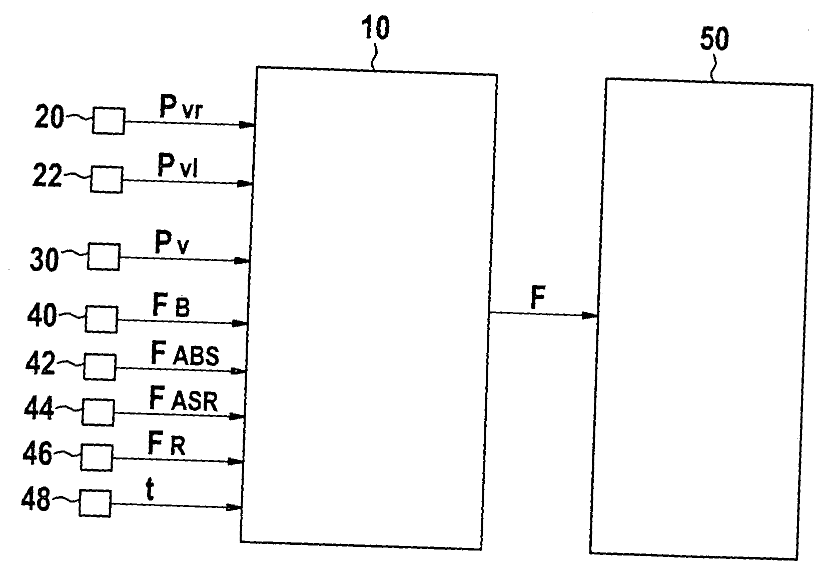
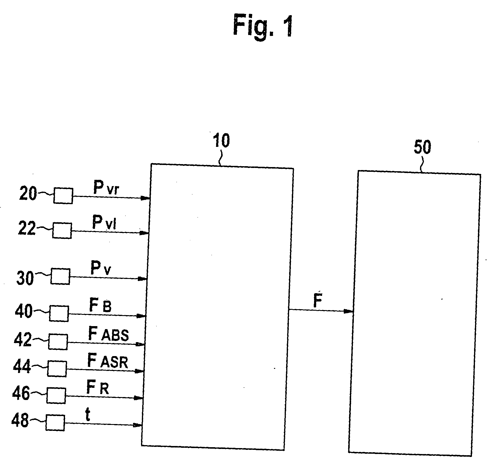
[0037]FIG. 1 illustrates an exemplary embodiment for monitoring a brake system. In the process, pressure signals pn of the wheel brakes at each individual axle are transmitted to block 10, the pressure signals representing the brake pressure. For clarity, however, only pressure signals pfr (20) and pfl (22) of an individual axle having two wheel brakes have been included in FIG. 1. pfr represents the brake-pressure signal in the front right wheel brake, and pfl represents the brake-pressure signal in the front left wheel brake. However, this may easily be expanded to a plurality of axles and to additional wheel brakes per axle. In addition to the pressure signals of the wheel brakes, block 10 is provided with pressure signal pa (30) for the admission pressure in the main cylinder.

[0038] Furthermore, state identifiers of braking interventions in the form of flags are forwarded to block 10. In this context, unset flag 0 corresponds to the operation of the brake system without braking...


PUM


Abstract

In a method and a device for monitoring a brake system, e.g., a wheel pressure sensor suite of a brake system of a motor vehicle, the fault detection is implemented on the basis of a differential threshold being exceeded by a signal that is representative for the difference of the brake pressures at the individual wheel brakes of a wheel axle. In the process, the differential threshold is set as a function of the averaged rate of increase of the individual pressures at the wheel brakes. Fault detection is carried out on the basis of a model, which takes the instantaneous operating state of the brake system into account.

Description

FIELD OF THE INVENTION [0001] The present invention relates to a method and a device for detecting a malfunction of a brake system, e.g., for detecting a malfunction of the wheel pressure sensor suite of a brake system of a motor vehicle during activation of the brake system as a function of two operating modes. The present invention also relates to a method and a device for operating a system, which controls and / or regulates the functions of a motor vehicle as a function of the detected malfunction. BACKGROUND INFORMATION [0002] In active steering systems, described, for example, in German Published Patent Application No. 38 26 982, the brake pressures are able to be detected at the separately controlled wheels of an axle and, sparing a dead zone, their difference ΔP may be utilized at low ΔP to obtain an additional steering angle δ. This considerably increases the driving stability during braking, in particular on uneven roadways. SUMMARY [0003] An example embodiment of the presen...

Claims


Application Information

Patent Timeline
IPC IPC(8): B60T8/88B60T8/94B60T17/22
CPCB60T8/885B60T2270/413B60T2270/402B60T17/22
Inventor WEEBER, KAIKNOOP, MICHAELLEIMBACH, KLAUS-DIETER
Owner ROBERT BOSCH GMBH
Learn More