Coil component

a coil and component technology, applied in the direction of transformer/inductance details, basic electric elements, inductances, etc., can solve the problems of difficult miniaturization, reduced relative permeability, and difficult to obtain high relative permeability in high frequency bands, and achieve excellent impedance characteristics

Active Publication Date: 2005-11-17
TDK CORPARATION
View PDF5 Cites 29 Cited by
  • Summary
  • Abstract
  • Description
  • Claims
  • Application Information

AI Technical Summary

Benefits of technology

[0016] An object of the invention is to provide a small and low-profile coil component excellent in impedance characteristic.

Problems solved by technology

The winding type coil has a problem that the miniaturization is difficult from the limitation in structure.
However, in any material, as the frequency of a current supplied to the coil conductors 133 and 135 becomes high, its relative permeability is decreased, and accordingly, there is a problem that high relative permeability is hard to obtain in a high frequency band.
Thus, the inductance of the coil conductors 133 and 135 can not be sufficiently increased, and there is a problem that it is difficult to sufficiently raise the impedance of the common mode choke coil 101.
Accordingly, when the common mode choke coil array is made smaller, the interval between the outermost peripheral part of the common mode choke coil element and the peripheral end part of the magnetic substrate becomes short, and part of the magnetic flux lines generated by the common mode choke coil element leaks to the outside of the common mode choke coil array, and there is a problem that the impedance can not be sufficiently raised.

Method used


Image

  • Coil component
  • Coil component
  • Coil component

Examples


first embodiment

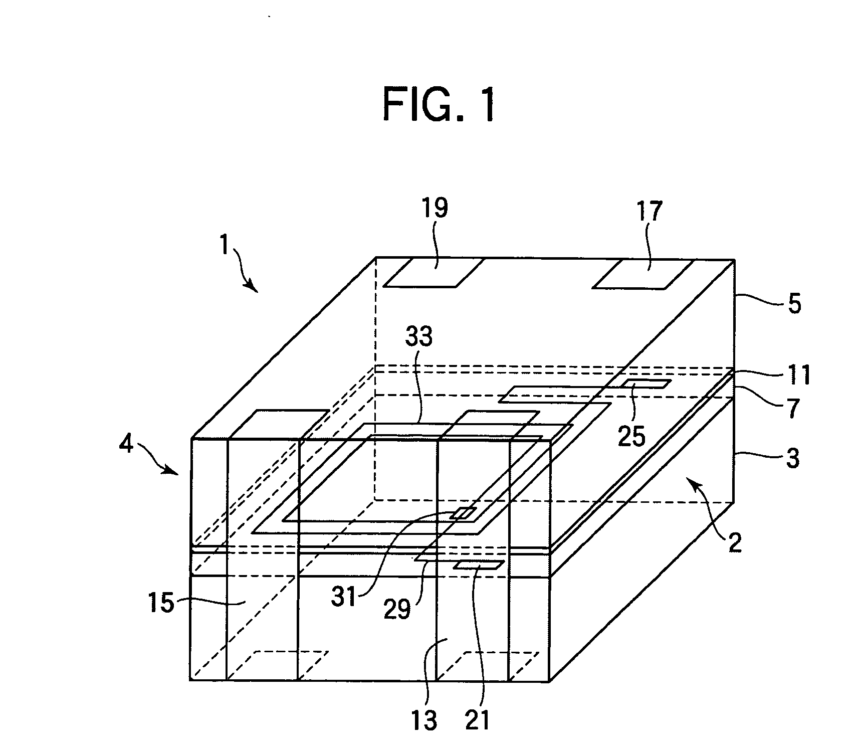
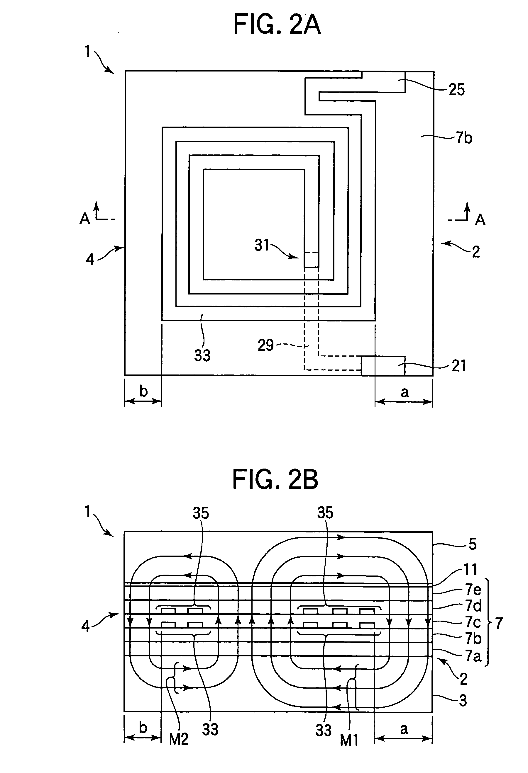
[0029] A coil component according to a first embodiment of the invention will be described with reference to FIGS. 1 to 3. In this embodiment, a description will be made while using, as an example of a coil component, a common mode choke coil to suppress a common mode current which causes electromagnetic interference in a balanced transmission system. FIG. 1 is a perspective view showing a common mode choke coil 1. In FIG. 1, in order to facilitate understanding, an internal electrode terminal 21, a coil conductor 33 formed in an insulating layer 7, a lead wire 29 connected to the coil conductor 33 and the through hole 31 via a through hole 31, and an internal electrode terminal 25 connected to the coil conductor 33, which are covered with an external electrode 13 and can not be originally seen, are shown in a transparent manner. Besides, the illustration of a coil conductor 35 and the like laminated on the coil conductor 33 via an insulating film is omitted.

[0030] As shown in FIG....

second embodiment

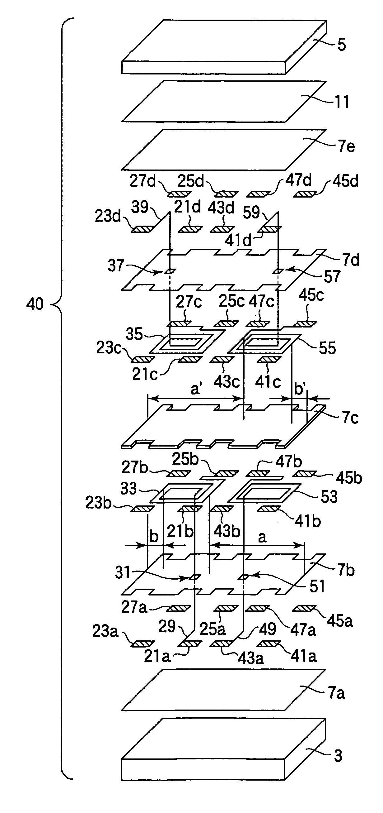
[0054] A coil component according to a second embodiment of the invention will be described with reference to FIGS. 4 and 5. In this embodiment, a description will be made while using, as an example of a coil component, a common mode choke coil array 40 in which two choke coils are arranged side by side. FIG. 4 is an exploded perspective view of the common mode choke coil array 40 according to this embodiment. Structural elements having the same operation and function as structural elements of the common mode choke coil 1 shown in FIG. 1 are denoted by the same characters and their explanation will be omitted.

[0055] As shown in FIG. 4, the common mode choke coil array 40 includes, on planes parallel to the opposite surfaces of magnetic substrates 3 and 5, a common mode choke coil including coil conductors 33 and 35 and lead wires 29 and 39 laminated via insulating films, and a common mode choke coil adjacent to the common mode choke coil and including coil conductors 53 and 55 and ...


PUM

PropertyMeasurementUnit
heightaaaaaaaaaa
vertical lengthaaaaaaaaaa

Abstract

The invention relates to surface-mount coil component including a mount surface mounted on a printed circuit board or a hybrid IC (HIC), and provides a small and low-profile coil component excellent in impedance characteristic. The coil component includes coil conductors each of which includes a major wiring region having the number N of wiring lines and a minor wiring region arranged to be opposite to the major wiring region and having the number (N−1) of wiring lines, and is arranged so that a major wiring side interval as an interval between an outermost periphery of the major wiring region and one side part of the substrate opposite thereto is longer than a minor wiring side interval as an interval between an outermost periphery of the minor wiring region and the other side part of the substrate opposite thereto.

Description

BACKGROUND OF THE INVENTION [0001] 1. Field of the Invention [0002] The present invention relates to a surface-mount coil component having a mount surface mounted on a printed circuit board or a hybrid IC (HIC). [0003] 2. Description of the Related Art [0004] As a coil component mounted on an inner circuit of an electronic equipment such as a personal computer or a cellular phone, there are known a winding type in which a copper wire is wound around a ferrite core, a lamination type in which a coil conductor pattern is formed on the surface of a magnetic sheet of ferrite or the like and the magnetic sheet is laminated, and a thin film type in which an insulating film and a coil conductor of a metal thin film are alternately formed by using a thin film formation technique. [0005] Patent document 1 (JP-A-8-203737) discloses a common mode choke coil as a thin film type coil component. Patent document 2 (JP-A-2003-217932) discloses, as a thin film type coil component, a common mode chok...

Claims


Application Information

Patent Timeline
Patent Type & Authority Applications(United States)
IPC IPC(8): H01F5/00H01F17/00H01F27/28
CPCH01F27/2804H01F17/0013
Inventor ITO, TOMOKAZUKUDO, TAKASHIOTOMO, MAKOTO
Owner TDK CORPARATION
Why Eureka
Try Eureka