Display apparatus and display system

a display system and display screen technology, applied in the field of display screens, can solve the problems of difficulty in providing sufficient space between the cameras, difficulty in distributing technology to households, and difficulty in creating a low-cost system, and achieve the effects of reducing the thickness of the display screen itself, reducing the cost of manufacturing, and simple system structur

Inactive Publication Date: 2005-11-17
DAI NIPPON PRINTING CO LTD
View PDF10 Cites 59 Cited by
  • Summary
  • Abstract
  • Description
  • Claims
  • Application Information

AI Technical Summary

Benefits of technology

[0036] (1) The wave transmission detection means detects outside electromagnetic waves or elastic waves transmitted to a plurality of different regions of the display screen, and based on the results of this detection, various functions of the display screen can be realized and its operability improved, such as imaging, detection of positions on the display screen indicated by the viewer, the detection of the position of the source of electromagnetic or elastic waves, etc.
[0037] (2) In particular, since the wave transmission detection means includes wave detection elements in each of the pixels of the display screen arranged together with the display element, the electromagnetic waves or elastic waves being transmitted to the display screen can be detected precisely. In addition, this enables the detection of electromagnetic waves or elastic waves transmitted to a distant pixel simply according to the size of the display screen.
[0038] (3) By connecting together the pair of the wave detection element and display element, with a gate electrode line, a source electrode line, and other parts, the display element and other constituent elements to realize the display features can be used to also make up the constituent elements for the detection features.
[0039] (5) By having a compound imaging system with a plurality of optical blocks, the imaging system can be made thinner in the direction of light propagation, which can restrain the thickness of the display screen itself. In addition, a plurality of parallax images can be obtained.
[0040] (7) Since a lens array is used for the compound imaging system, the structure of the system is simple and the manufacturing cost can be restrained. In addition, the lens array is arranged so as to form an image of the subject facing the display screen in a center of the corresponding plurality of photoelectric conversion elements, and as a result, this prevents the image of a subject formed by the lens from being away from the light-receiving parts of the photoelectric elements.
[0041] (13) Since the image data generation means generates the image data in correspondence with the distance determined by the distance determination means, the parameters for creating the image data are increased, and the precision of the generated image data can be improved.

Problems solved by technology

However, in moving the camera as explained above to generate the 3D image, there are problems such as the time axis and the need for space for the camera.
These problems have made it particularly difficult for the technology to spread to households.
In addition, with a plurality of cameras arranged at multiple points, there are the difficulties in providing sufficiently large spaces between the cameras and in creating a low-cost system.
In this situation, using a mouse would not be convenient, as the viewer would need to have a space to use the mouse, etc.
The viewer can use a keypad on the remote control to enter information by pressing the buttons, but this has a low operability because the options are limited.
With these television phones, however, when the two parties are watching each other's image as they speak, the displayed image of the other party is not a normal and accurate image.
There is also the problem that the speaker cannot see the image and expression of the other party properly if he is looking at the camera.

Method used


Image

  • Display apparatus and display system
  • Display apparatus and display system
  • Display apparatus and display system

Examples


first embodiment

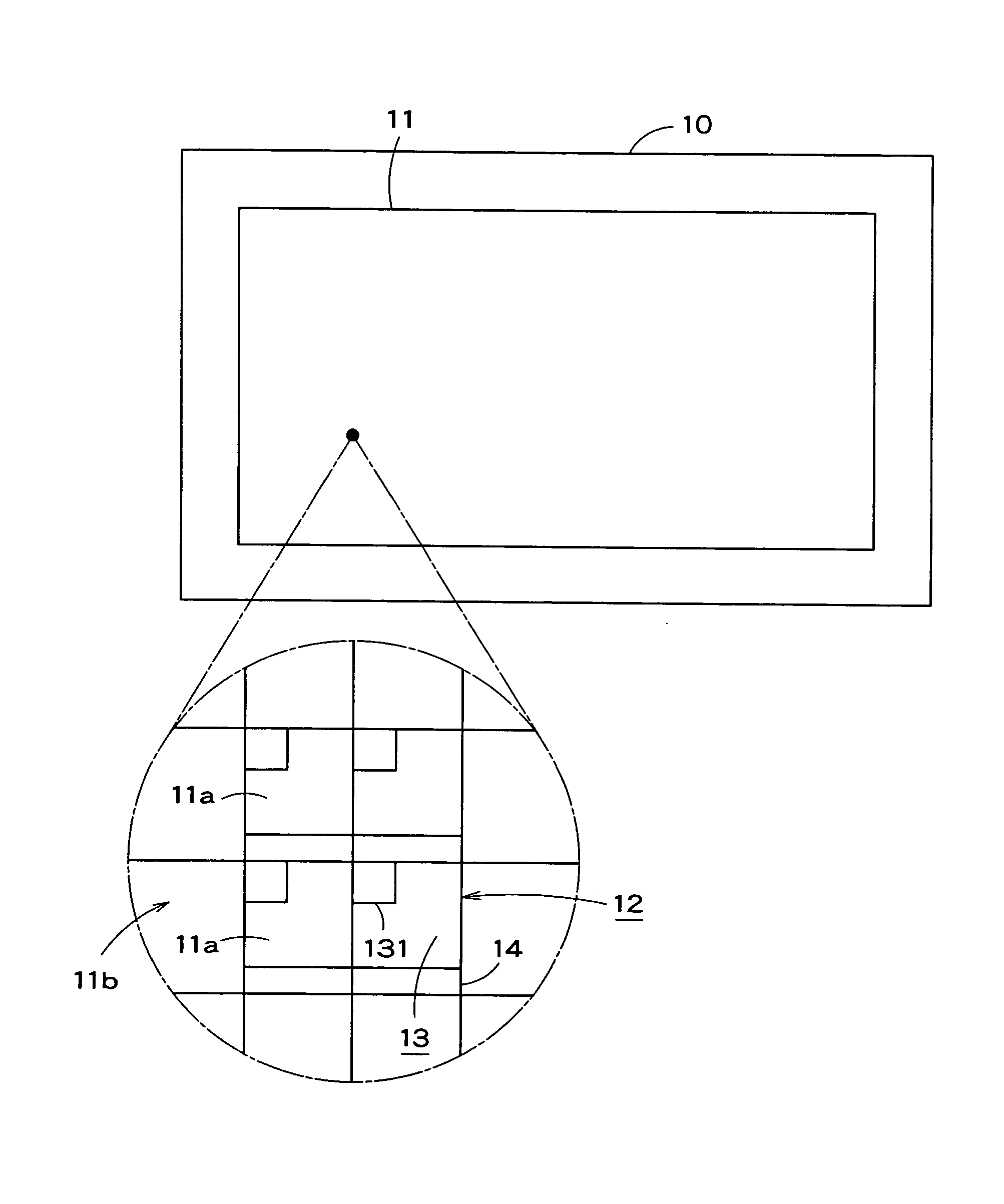
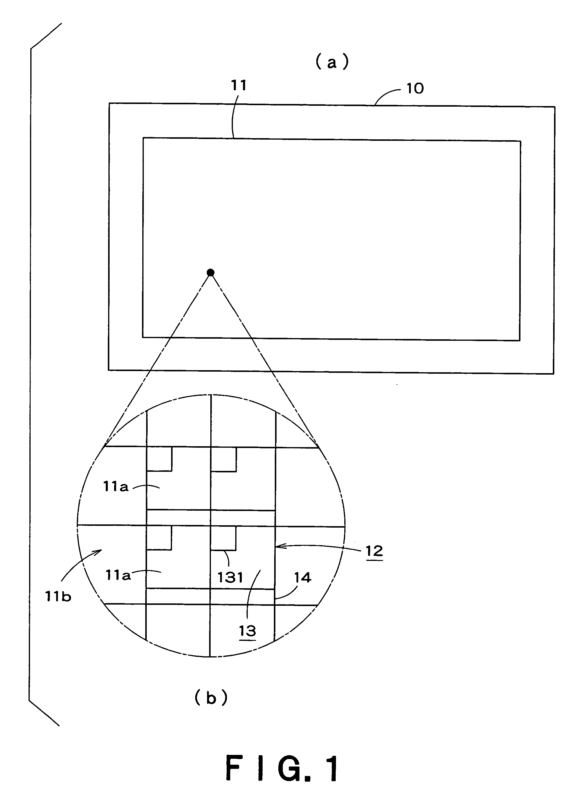
[0053]FIG. 1 shows a display apparatus according to embodiment 1 of the present invention. FIG. 1(a) is a front view of the display apparatus and FIG. 1(b) is a perspective view of a part of FIG. 1(a).

[0054] A display screen 10 has both a color display function and a color imaging function.

[0055] As shown in FIG. 1, the display apparatus 10 has a large 100-inch display screen 11 comprised of a plurality of pixels 11b, for example, 1080 pixels high and 1920 pixels wide (1.2 m×2.2 m). The display screen 11 has two plastic substrates filled with liquid crystal (or glass substrates, but if the display screen 11 of the display apparatus 10 is large in size, plastic substrates are preferable). The display apparatus 10 uses an active matrix-driven display in which striped-shaped electrodes are arranged in a cross pattern so that the pixels form a matrix.

[0056] The display apparatus 10 also has display imaging modules 12 formed in each of a plurality of sub-pixels 11a. Each display imagi...

second embodiment

[0080] FIGS. 6(a)(b)(c) illustrate the present invention according to the second embodiment. FIG. 6(a) is a front view of the display apparatus, FIG. 6(b) is a perspective view of a part of FIG. 6(a), and FIG. 6(c) is a cross-sectional view of FIG. 6(b) along line P-P′.

[0081] The parts shown in FIGS. 6(a)-(c) have the same numerals as the parts shown in FIGS. 1-5, and therefore detailed explanation of the parts will be omitted.

[0082] As shown in FIGS. 6(a)(b)(c), the display apparatus 10 is the same size as in the first embodiment and formed of the same parts. The display screen 11 of the display apparatus 10 has display imaging modules 12a, each including imaging elements 14a. The display imaging module 12a is formed in each of the sub-pixels 11a. In addition, each of the display imaging modules 12a has an imaging lens 211a, which forms an image of the subject in a light-receiving part of imaging element 14a, and a light shield 22a, which prevents interference of light signals en...

embodiments

(Modification of Embodiments)

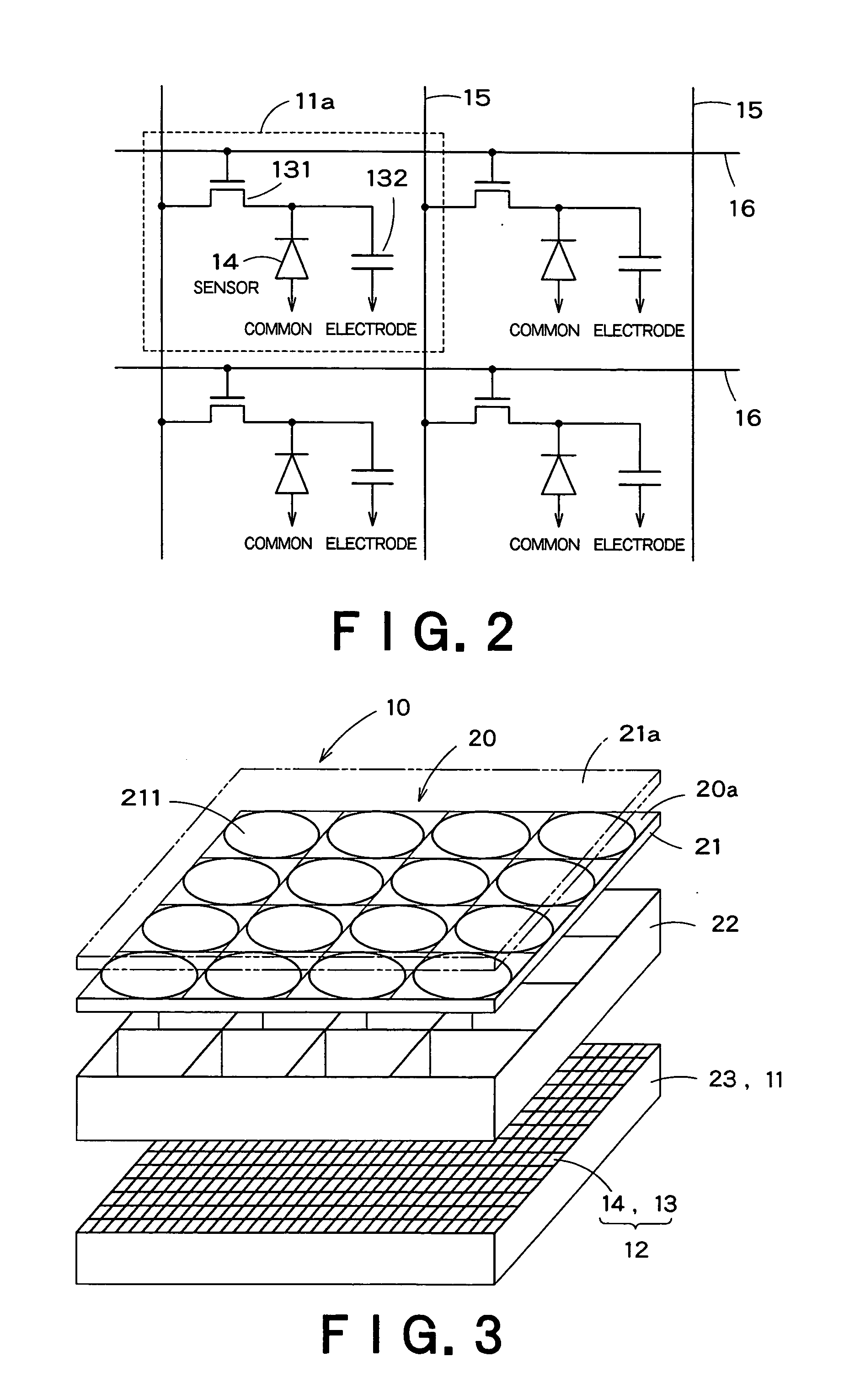
[0085] The present invention is not limited to the first and second embodiments, and various modifications can be made within the scope of the present invention. For example, in each of the embodiments, the display apparatus 10 may include apertures 21a on the outside of the imaging lenses 211, 211a forming the optical blocks 20a, to restrict the amount of entering light (refer to FIG. 3). The apertures 21a are formed of a light-shielding plate material and the number of the apertures 21a corresponds to the number of imaging lenses 211, 211a, with the size of the openings corresponding to the size of each of the view regions of the imaging lenses 211, 211a. By using the apertures 21a, the scope of an image of a subject formed by the imaging lenses 211, 211a in the light-receiving part of the light sensors 14 or the imaging elements 14a can be limited.

[0086] In each of the first and second embodiments, the imagining lenses 211, 211a can be angled with re...


PUM


Abstract

A display apparatus 10 has a display screen 11 comprised of plurality of pixels displaying images based on image data, light sensors 14 to detect light entering the display screen 11 and arranged with display elements 13 to form the pixels, and compound imaging systems 20 comprised of imaging lenses 211 forming images of a subject in the light-receiving part of the light sensors 14. Images of a subject are output from the plurality of light sensors 14, and a signal processing circuit 35 synthesizes the image signals to generate image data. The image displayed by the display screen 11 is based on the image data output by the signal processing circuit 35.

Description

BACKGROUND OF THE INVENTION [0001] 1. Field of the Invention [0002] The present invention relates to a display apparatus which displays images based on image data, and a display system. [0003] 2. Background Art [0004] In recent years, displays have been developed to provide the viewer with a strong sense of nearness to a projected image. These virtual reality displays are required to display wide-view images on large-sized screens, at the same time the images must be of high resolution and density. Displaying wide-view images on a large screen provides the width and depth needed to increase the realism of the image. In this way, the space of the image and the space of the viewer merge, with the effect that the viewer is drawn into the space of the image. [0005] As types of virtual reality displays, there are a large-screen liquid crystal apparatus and a display apparatus to display 3D (three-dimensional) images. In the conventional method for producing an image of a subject, when cr...

Claims


Application Information

Patent Timeline
Patent Type & Authority Applications(United States)
IPC IPC(8): G09F9/30G09G3/36G09G3/20G09G5/00H04N13/00H04N13/02
CPCG06F3/0412G09G3/003H04N7/144G09G2360/142G09G3/20G06F3/042
Inventor SAKAMAKI, TERUOWATANABE, MASACHIKA
Owner DAI NIPPON PRINTING CO LTD
Why Eureka
Try Eureka