Communication message conversion device, communication method and communication system

a communication message and conversion device technology, applied in the direction of data switching by path configuration, radio/inductive link selection arrangement, electrical equipment, etc., can solve the problems of large time and cost, difficult to divert the existing system and control software and development technology designed for an event-driven communication protocol, and the need for significant design changes in the system. , to achieve the effect of reducing the burden of conversion processing or transfer processing and improving transmission efficiency

Active Publication Date: 2005-11-17
RENESAS ELECTRONICS CORP
View PDF4 Cites 135 Cited by
  • Summary
  • Abstract
  • Description
  • Claims
  • Application Information

AI Technical Summary

Benefits of technology

[0032] According to the communication message conversion device, the communication method and the communication system of the present invention, since communication channels having different communication protocols can be relayed, existing communication devices will be able to use the new communication protocol. Further, since the received message is sorted into a plurality of buffer areas according to the message identifier, the subsequent proces

Problems solved by technology

Meanwhile, the amount of information communicated among the units has continued to increase due to demands of sophistication of the control system.
In a conventional communication system, when introducing a time-triggered communication protocol (such as FlexRay) in order to improve the reliability of the dispersive real-time control system, secure the network bandwidth, and determine the amount of delay, it is difficult to divert the existing system and control software and development technology designed for an event-driven communication protocol (such as CAN).
In such a case, in order to make a transition from a conventional event-driven task control system to a time-driven task control system, much time and cost will be required for the significant design change in the system and for the broad reexamination procedures.
The following drawbacks will arise when adopting the conventional technology capable of realizing the foregoing functions in the present technical field.
For examp

Method used


Image

  • Communication message conversion device, communication method and communication system
  • Communication message conversion device, communication method and communication system
  • Communication message conversion device, communication method and communication system

Examples


Embodiment Construction

[0047] The invention will be now described herein with reference to illustrative embodiments. Those skilled in the art will recognize that many alternative embodiments can be accomplished using the teachings of the present invention and that the invention is not limited to the embodiments illustrated for explanatory purposed.

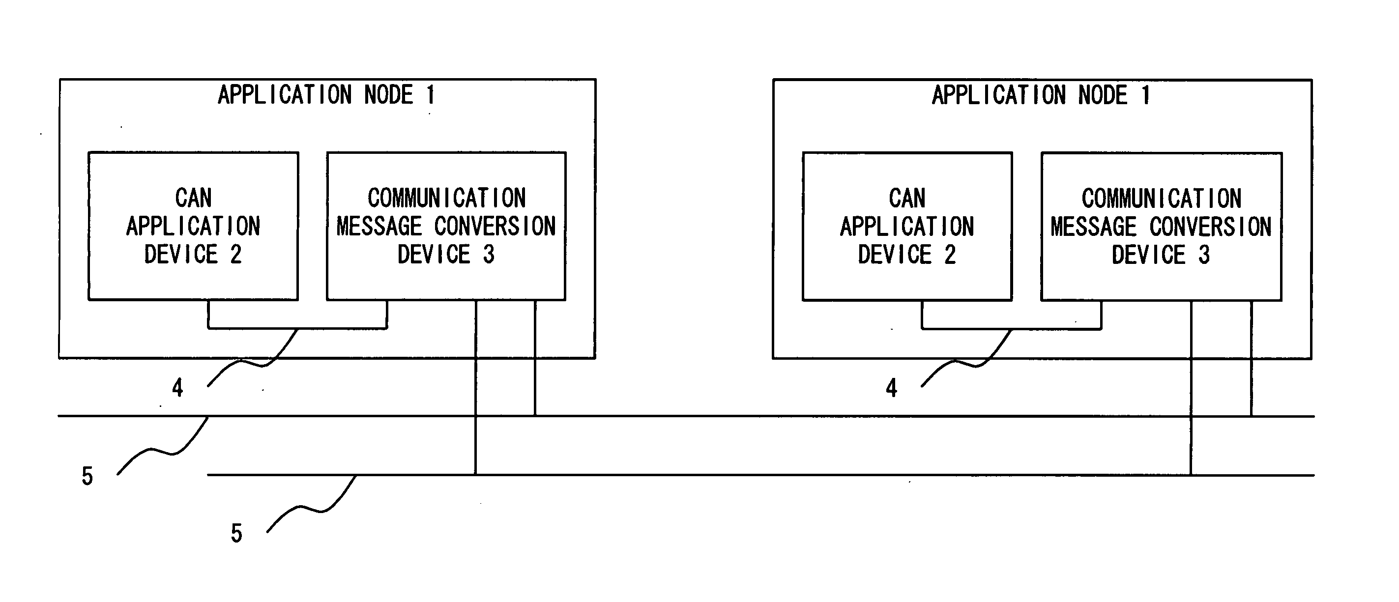
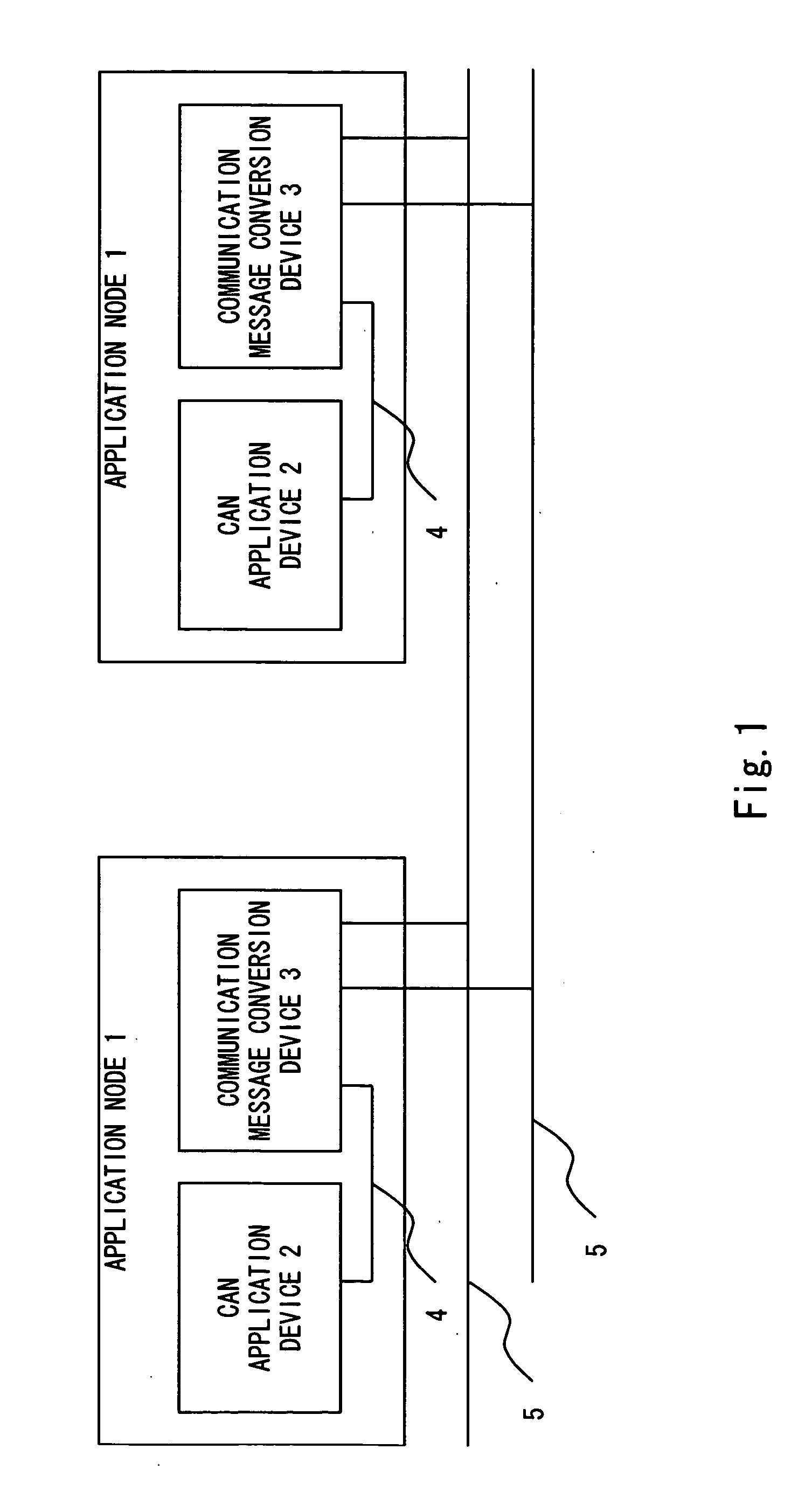
[0048] First, the configuration example of the communication system according to an embodiment of the present invention is explained with reference to FIG. 1. This communication system, as shown in FIG. 1, comprises two application nodes 1, and the two application nodes 1 are connected communicably via a FlexRay transmission channel 5. In this example, although two application nodes 1 are provided, this is not limited thereto, and an arbitrary number of application nodes 1 may be provided.

[0049] This communication system, for instance, is an in-car LAN provided inside vehicles or the like, and FlexRay (second communication protocol) as an example of the time-t...


PUM


Abstract

A communication message conversion device according to the present invention comprises a first receiving unit receiving a first message according to a first communication protocol, a first message storage unit storing the first message received by the first receiving unit in one of a plurality of buffer areas according to a first message identifier contained in the first message, a first identifier conversion unit converting the first message identifier contained in the first message stored in the first message storage unit into a second message identifier, a first message conversion unit packing a plurality of first messages converted with the first identifier conversion unit into a second message and a first transmission unit transmitting the second message converted with the first message conversion unit according to a second communication protocol.

Description

BACKGROUND OF THE INVENTION [0001] 1. Field of the Invention [0002] The present invention generally relates to a communication message conversion device, a communication method and a communication system, and in particular to a communication message conversion device, a communication method and a communication system to be connected to different communication protocol channels. [0003] 2. Description of the Related Art [0004] In recent years, the number of electronic equipment to be mounted in vehicles is increasing, and an in-car LAN is being widely used to prevent the increase in the number of wire harnesses for connecting such electronic devices. [0005] For example, with the in-car LAN, the application nodes of Electric Control Units (ECU) and the like provided to the engine control device, transmission control device, and control devices for ABS, dashboard indicators, lights and power windows are connected communicably, and various controls are performed thereby. [0006]FIG. 11 sh...

Claims


Application Information

Patent Timeline
IPC IPC(8): H04L12/46H04L12/28H04L29/06H04L29/08H04Q7/00
CPCH04L67/12H04L67/2871H04L69/08
Inventor FUJIMORI, TAKASHI
Owner RENESAS ELECTRONICS CORP
Why Eureka
Try Eureka