Optical disk device

a technology of optical disk and optical disc, which is applied in the field of optical disk devices, can solve the problems of increasing the distance between the halt position of commercial skipping and the user, the inability to visually confirm that a commercial has been skipped correctly, and the inability to immediately cope with the scan off command. to achieve the effect of quick skip imag

Inactive Publication Date: 2005-11-17
FUNAI ELECTRIC CO LTD
View PDF3 Cites 0 Cited by
  • Summary
  • Abstract
  • Description
  • Claims
  • Application Information

AI Technical Summary

Benefits of technology

[0021] According to the optical disk device of the invention, the skip function can be obtained by using the fast forward function and the time search function. Further, when the skip mode is initiated, the fast forward function performs fast forward reproduction for a predetermined period of time that is shorter than a specified period of time, and thereafter, the time search function searches ahead, for a reproduced image at a location corresponding to the specified period of time, and the mode is shifted from the skipmode to the normal reproduction mode. Therefore, in the skip mode, a user can confirm the skipping state while viewing the reproduced images that are skipped during fast forward reproduction, and can

Problems solved by technology

Since unlike a video cassette recorder an optical disk device does not linearly perform fast forward reproduction, the pre-reading of image data for a specific time ahead is required.
Further, when after the image data A32 at the location for thirty-two seconds have been reproduced a scan off command is issued while a CPU that controls the entire device is cur

Method used


Image

  • Optical disk device
  • Optical disk device
  • Optical disk device

Examples


Embodiment Construction

[0027] One embodiment of the present invention will now be described while referring to the drawings.

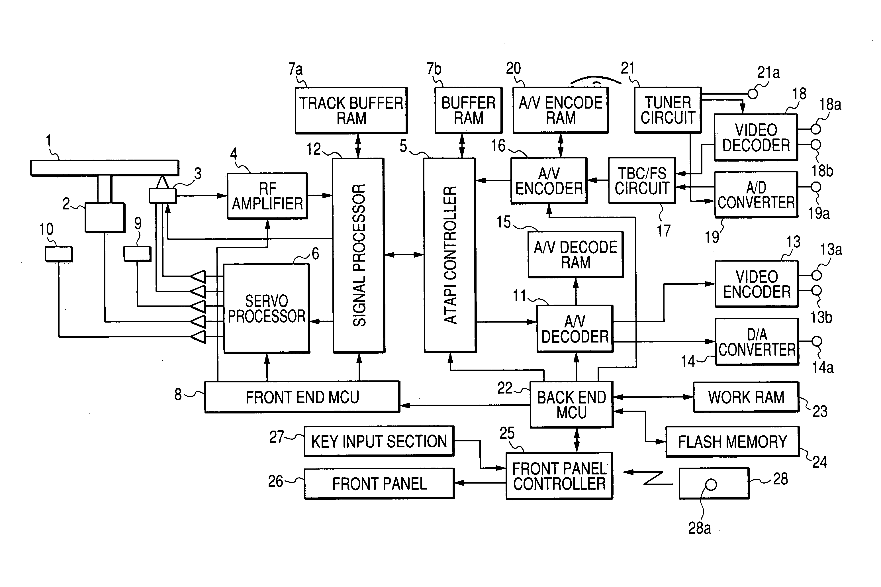
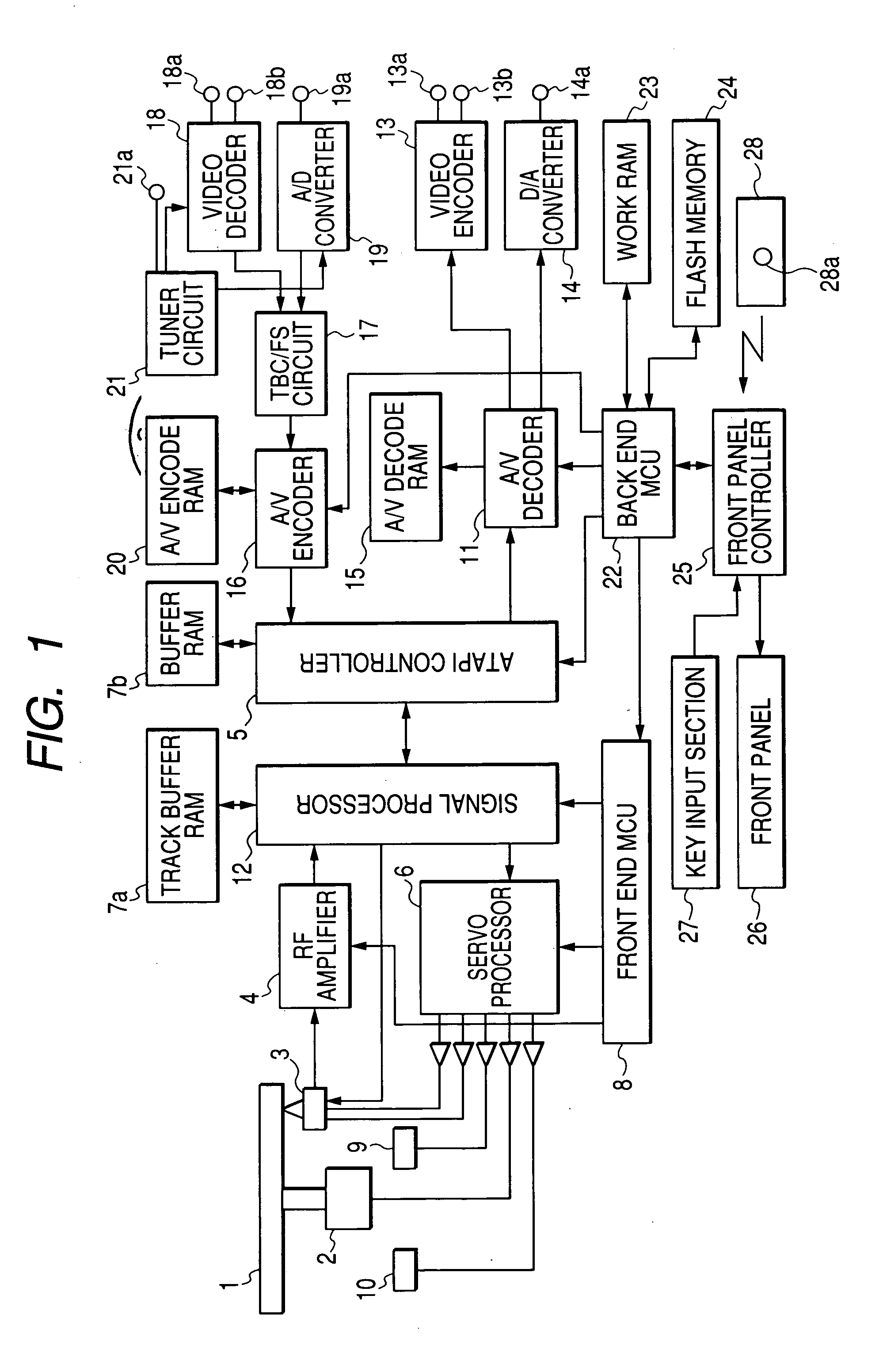
[0028]FIG. 1 is a circuit block diagram showing a DVD recorder constituting an optical disk device according to the embodiment of the present invention.

[0029] In FIG. 1, an optical pickup 3 detects information on an optical disk 1 rotated by a disk motor 2, and outputs the information, via an RF amplifier 4, to an ATAPI controller 5 and a signal processor 12. A track buffer RAM (e.g., an SDRAM) 7a, which is connected to the signal processor 12, is used to temporarily store data that are amplified by the RF amplifier 4 and decoded in accordance with a DVD standard (in this embodiment, data are compressed using the MPEG (Moving Picture Experts Group) standard). The RF amplifier 4 and the signal processor 12 are controlled by a front end MCU 8.

[0030] In accordance with a command, and control data exchanged with the front end MCU 8 via the signal processor 12, a servo processor 6 prov...


PUM


Abstract

When a skip mode is initiated, a back end MCU employs a fast forward function to perform fast forward reproduction for a period of twenty-four seconds, for example, that is shorter than a skipping period of thirty seconds, for example, and thereafter, a time search function searches for a reproduced image at a location thirty seconds ahead. Thereafter, the skip mode is shifted to the normal reproduction mode.

Description

BACKGROUND OF THE INVENTION [0001] 1. Field of the Invention [0002] The present invention relates to an optical disk device having a skip function for skipping reproduced images for a specified period of time during the reproduction of information recorded on a recording medium. [0003] 2. Description of the Related Art [0004] The widespread use of optical disk devices, such as DVDs, for handling recording media has rapidly become an actuality. [0005] In addition to the audio and video data that are recorded on such optical disks, which includes DVDs, address data, for data recording locations (track positions), are also recorded and are used for random access searches. Included with the address data made available for such searches are time address data, which provide the total time that has elapsed following the initiation, at a start position, of the recording of video data. [0006] In this case, provided for an optical disk device is a time search function that employs the time ad...

Claims


Application Information

Patent Timeline
IPC IPC(8): G11B20/10G11B27/00G11B27/10H04N5/781H04N5/783H04N5/85H04N9/804
CPCG11B27/005G11B27/105H04N9/8042H04N5/783H04N5/85G11B2220/2562
Inventor NANBA, YOUSUKE
Owner FUNAI ELECTRIC CO LTD
Why Eureka
Try Eureka