Expansion machine

a technology of expansion machine and expansion plate, which is applied in the direction of machines/engines, positive displacement liquid engines, piston pumps, etc., can solve the problems of increased sliding resistance and abnormal wear

Inactive Publication Date: 2005-11-17
HONDA MOTOR CO LTD
View PDF6 Cites 1 Cited by
  • Summary
  • Abstract
  • Description
  • Claims
  • Application Information

AI Technical Summary

Benefits of technology

[0008] In accordance with this arrangement, by employing a simple arrangement in which the axis of the swash plate is offset toward the exhaust stroke side of the axial piston cylinder group relative to the axis of the rotor, it is possible to offset the locus of the contact points between the spherical depressions of the swash plate and the spherical projections of the pistons toward the expansion stroke side of the axial piston cylinder group.

Problems solved by technology

As a result, the piston receives a bending moment or a radially biased load, and the bending moment or radially biased load causes galling on sliding faces of the piston and the cylinder, thus giving rise to the problems of increased sliding resistance and the occurrence of abnormal wear.

Method used


Image

  • Expansion machine
  • Expansion machine
  • Expansion machine

Examples


Embodiment Construction

[0027] One embodiment of the present invention is explained below with reference to the attached drawings.

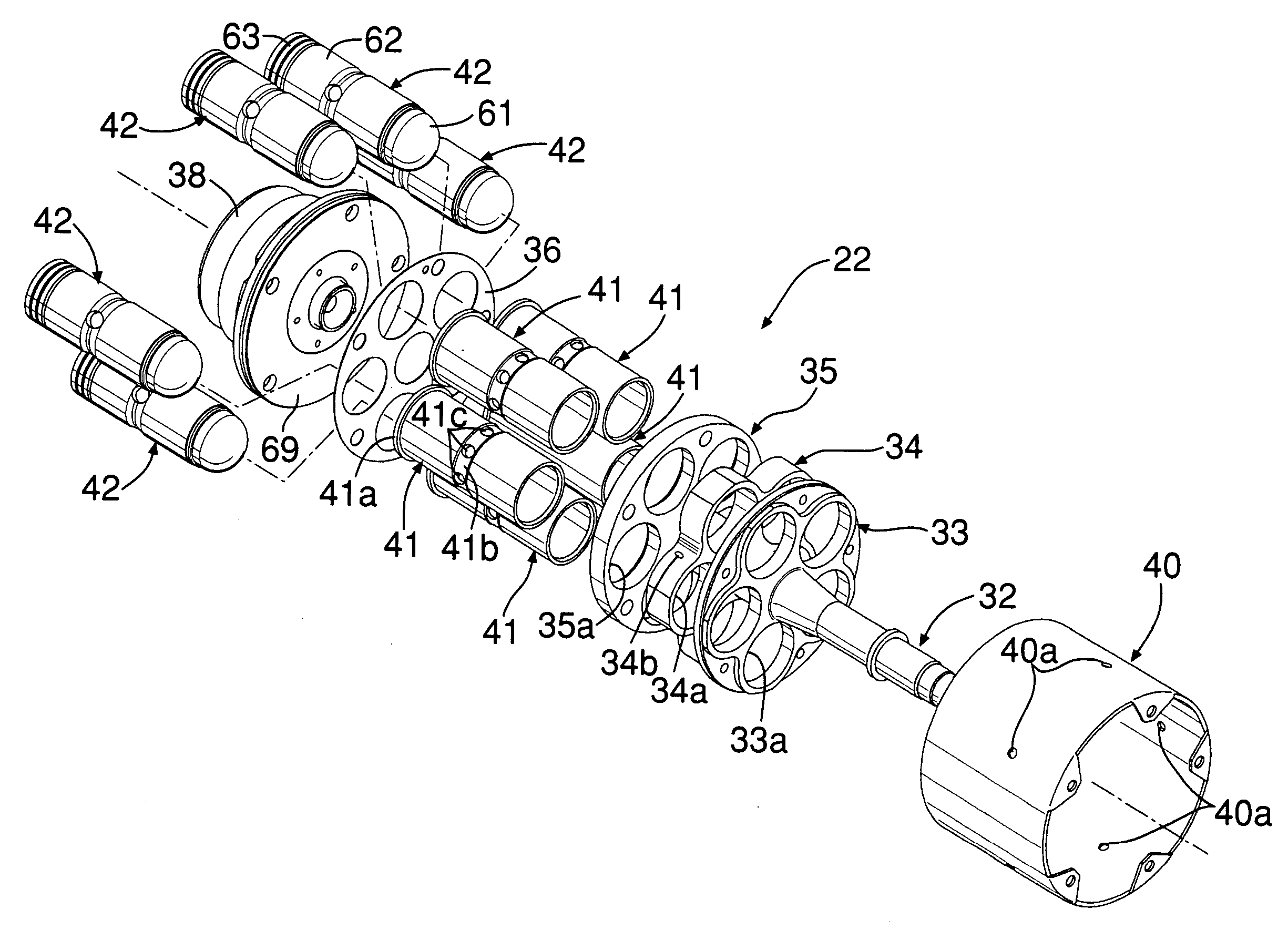
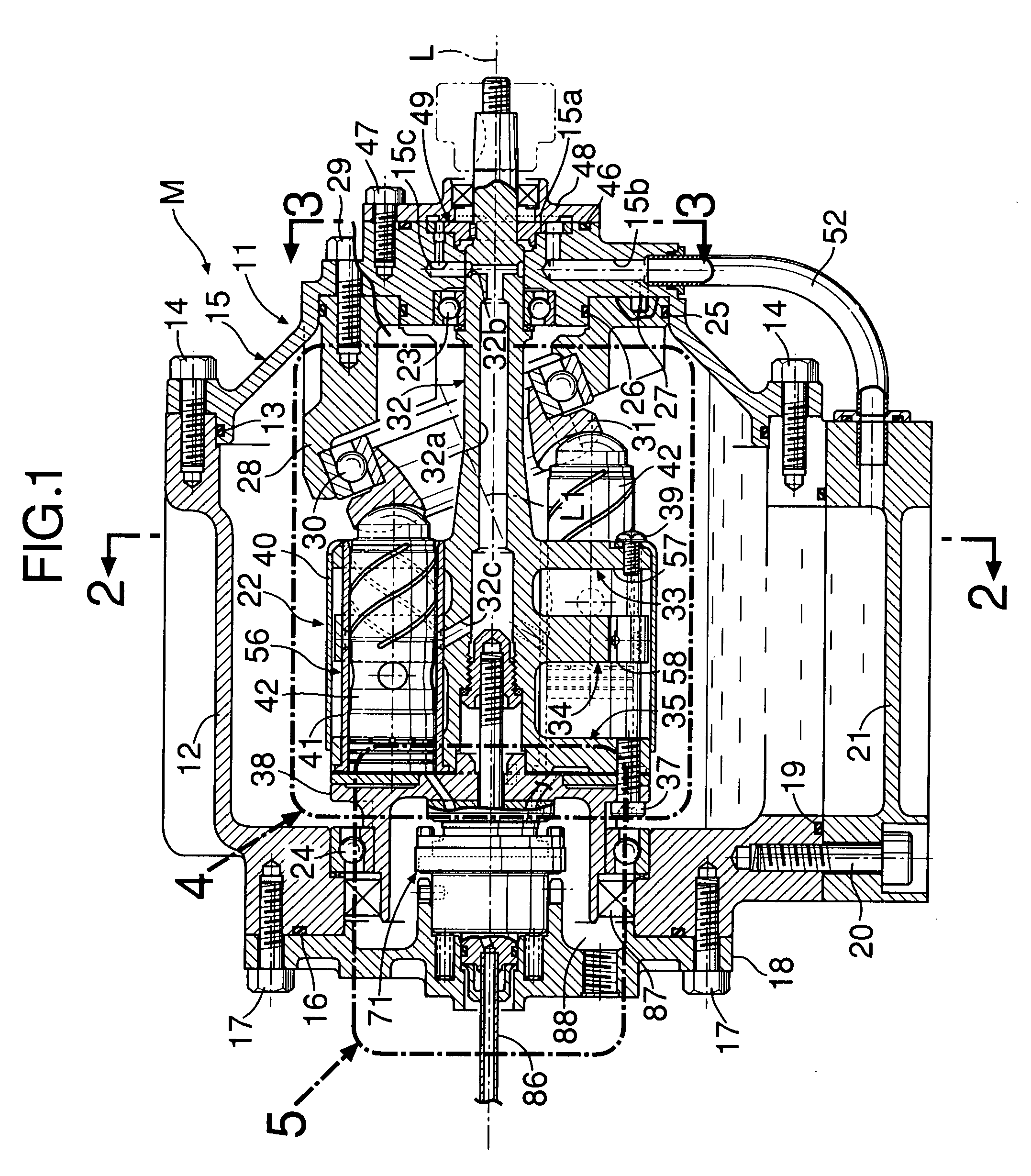
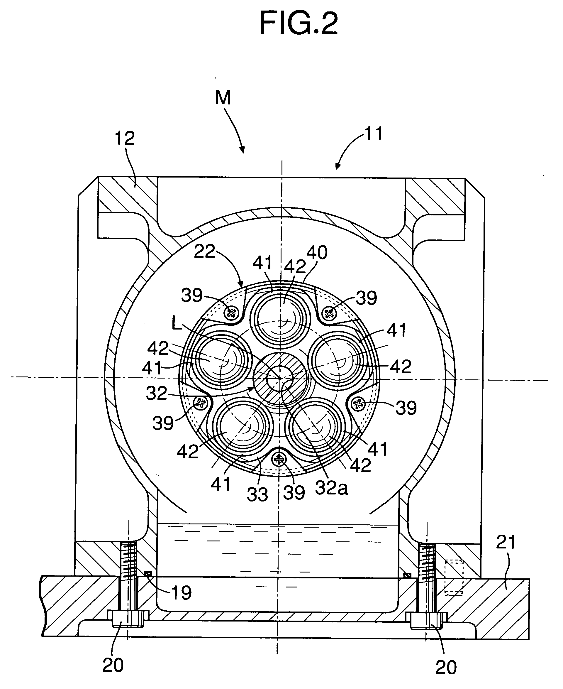
[0028] As shown in FIG. 1 to FIG. 9, an expander M of this embodiment is used in, for example, a Rankine cycle system, and converts the thermal energy and the pressure energy of high-temperature, high-pressure steam as a working medium into mechanical energy and outputs it. A casing 11 of the expander M is formed from a casing main body 12, a front cover 15 joined via a seal 13 to a front opening of the casing main body 12 by a plurality of bolts 14, a rear cover 18 joined via a seal 16 to a rear opening of the casing main body 12 by a plurality of bolts 17, and an oil pan 21 joined via a seal 19 to a lower opening of the casing main body 12 by a plurality of bolts 20.

[0029] A rotor 22 disposed rotatably around an axis L extending in the fore-and-aft direction in the center of the casing 11 has a front part thereof supported by a ball bearing 23 provided in the front cover 15 ...


PUM


Abstract

An expander is provided in which spherical projections (61a) formed at the forward end of pistons (42) of an axial piston cylinder group abut against spherical depressions (31a) formed in a swash plate (31), and an elliptical contact point locus (T) of contact points (p) between the spherical depressions (31a) and the spherical projections (61a) is offset toward the expansion stroke side of the axial piston cylinder group. As a result, in a middle region of the expansion stroke where the speed of the piston (42) is high and the surface pressure of the contact point (p) is high, the position of the contact point (p) can be made as close as possible to an axis (L3) of the spherical depression (31a) and an axis (L2) of the piston (42), thus reducing a bending moment and a radially biased load exerted on the piston (42) and minimizing any increase in sliding resistance and any occurrence of abnormal wear.

Description

FIELD OF THE INVENTION [0001] The present invention relates to an expander in which an axial piston cylinder group is arranged annularly in a rotor so as to surround an axis of the rotor, the rotor being rotatably supported in a casing, and spherical projections formed at the forward end of pistons of the axial piston cylinder group abut against spherical depressions formed in a swash plate. BACKGROUND ART [0002] A hydraulic device in which a spherical projection formed at the forward end of a piston of an axial piston cylinder group abuts against a spherical depression formed in a swash plate is known from Japanese Patent Application Laid-open No. 61-274166. By making the spherical projection abut against the spherical depression it is possible to reduce the surface pressure in the area where the two abut against each other and prevent relative rotation between the swash plate and the piston, thereby contributing to a reduction in wear of the swash plate and the piston. Moreover, s...

Claims


Application Information

Patent Timeline
Patent Type & Authority Applications(United States)
IPC IPC(8): F01B3/00F01B3/02
CPCF01B3/0017
Inventor MAKINO, HIROYUKIOOSONO, KOHEI
Owner HONDA MOTOR CO LTD
Why Eureka
Try Eureka