Fuel cell stack and fastening and reinforcing mechanisms for a fuel cell stack

a fuel cell and stack technology, applied in the field of fuel cells, can solve the problems of increasing the overall volume of the stack, increasing the cost and time needed for assembly and disassembly, and difficult to use the stack in a small fuel cell, and achieve the effect of simplifying the fastening structur

Inactive Publication Date: 2005-11-17
SAMSUNG SDI CO LTD
View PDF6 Cites 18 Cited by
  • Summary
  • Abstract
  • Description
  • Claims
  • Application Information

AI Technical Summary

Benefits of technology

[0014] In accordance with the present invention a simplified fastening structure for a stack in a fuel cell is provided, as well as a fuel cell system including the stack. Reinforcing structures for a fuel cell stack are also presented.

Problems solved by technology

However, the conventional structure described above requires many components such as bolts, nuts, and a fastening rod washer, which increase the cost and the time needed for assembly and disassembly.
In addition, this conventional structure increases the overall volume of the stack, making it difficult to use the stack in a small fuel cell.

Method used


Image

  • Fuel cell stack and fastening and reinforcing mechanisms for a fuel cell stack
  • Fuel cell stack and fastening and reinforcing mechanisms for a fuel cell stack
  • Fuel cell stack and fastening and reinforcing mechanisms for a fuel cell stack

Examples


first embodiment

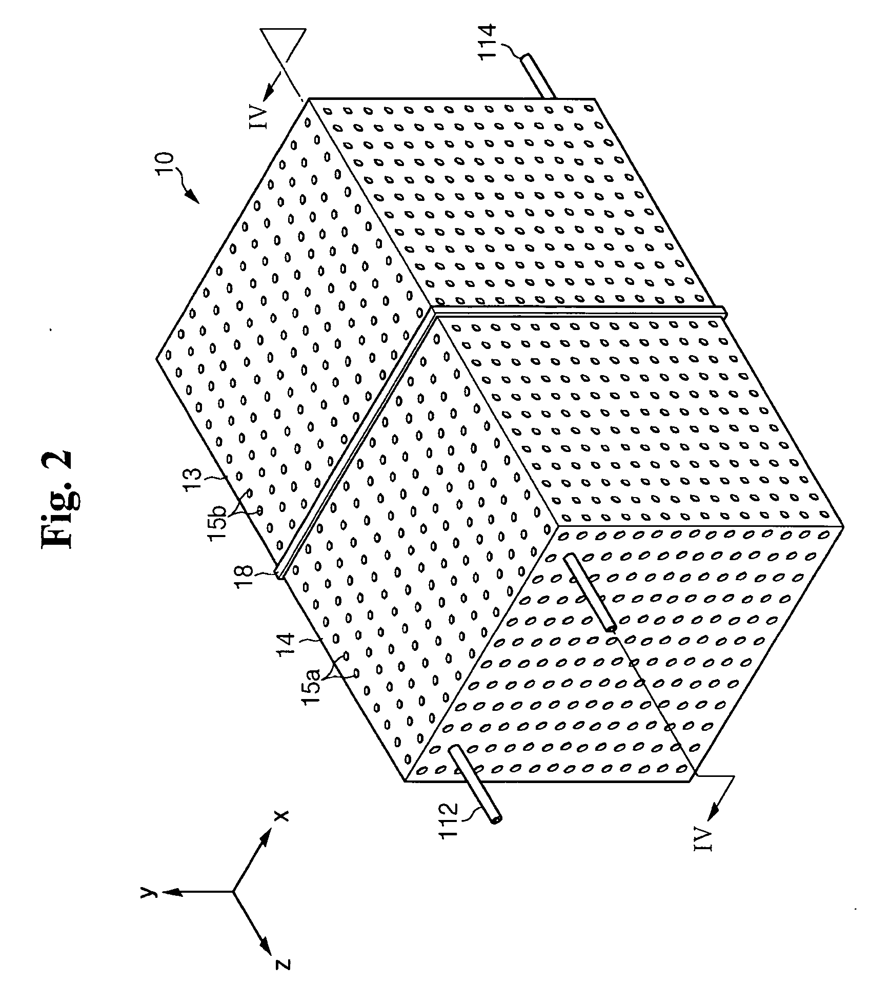
[0047]FIG. 2 is a perspective view illustrating a stack of a fuel cell system, according to the present invention, and FIG. 3 is an exploded perspective view illustrating the stack of the fuel cell system of FIG. 2. FIG. 4A is a cross-sectional view taken along Line IV-IV of FIG. 2. FIG. 4B is an enlarged view of the portion “A” shown in FIG. 4A.

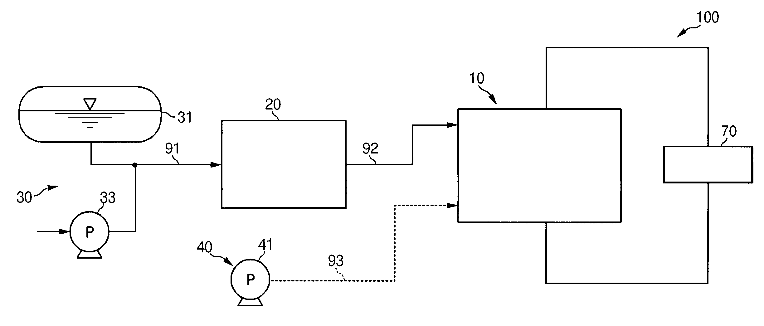
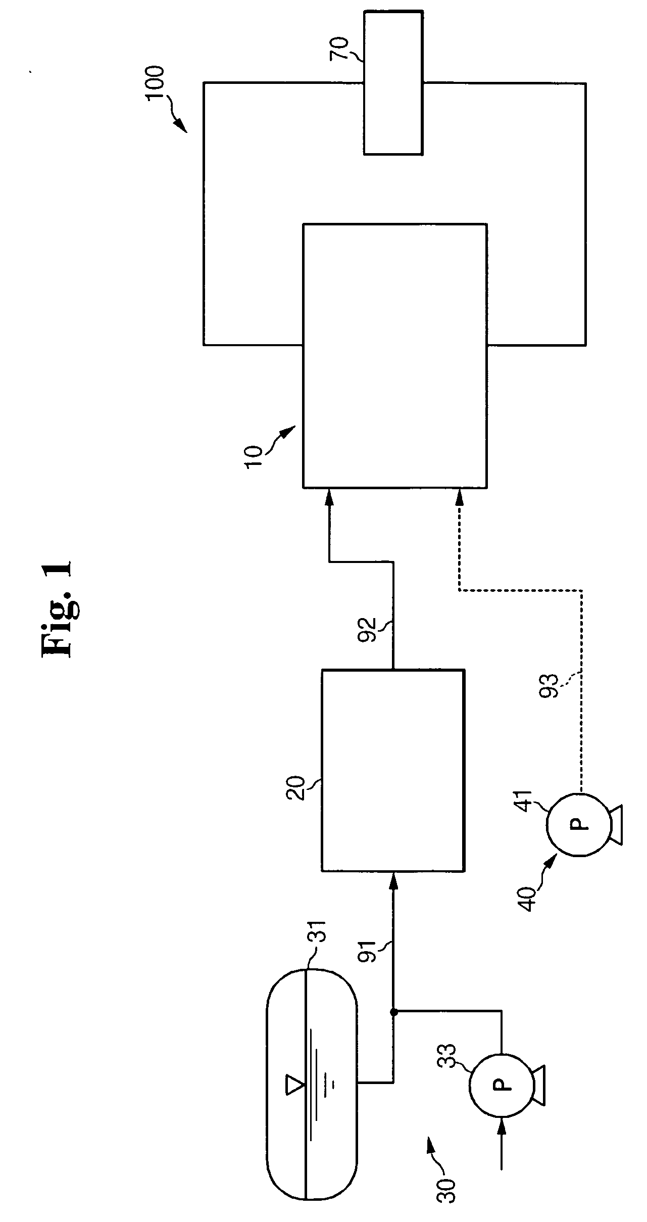
[0048] As shown in FIGS. 2, 3, and 4A, the stack 10 used in the fuel cell system 100 includes at least one electricity generator 11. Each electricity generator 11 causes an oxidation and reduction reaction between the hydrogen gas reformed by the reformer 20 and the oxygen obtained from external air in order to generate electric energy. Each electricity generator 11 constitutes a unit cell for generating electricity.

[0049] The electricity generator 11 includes a MEA 11a which oxidizes and reduces the hydrogen gas and the air, and separators 11b which supply the hydrogen gas and the air to the MEA. In the electricity generator 11, the separa...

second embodiment

[0068] The housing 53 and the cover 54, shown in FIG. 7B, include the L-shaped bent portions 534 and 544 of the However, the present invention is not limited to the arrangement shown and the housing 53 and the cover 54 may be welded using a variety of arrangements and shapes.

[0069]FIG. 8A is a cross-sectional view illustrating a stack of a fuel cell system according to a fourth embodiment of the present invention. FIG. 8B is an enlarged view of the portion “D” shown in FIG. 8A. In this embodiment, the orientation of the stacks of electricity generators 11 has changed with respect to the previous embodiments. In FIG. 8A, in the fourth embodiment of the present invention, the electricity generators 11 are stacked between both side surfaces 13b of the housing 13 such that the membrane-electrode assemblies 11a and the separators 11b are substantially perpendicular to the bottom surface 13a of the housing 13. In this embodiment, passages 13r and 14r for the inlet 112 and the outlet 114 ...

fifth embodiment

[0072]FIG. 9 is a perspective view illustrating a stack of a fuel cell system according to the present invention. In this embodiment, the housing, the cover, or both may have corrugated surfaces for increased rigidity and strength. Concave portions 63a and 64a and convex portions 63b and 64b, which extend longitudinally, are alternately arranged on the surfaces of a housing 63 and a cover 64.

[0073] The rigidity of the housing 63 and the cover 64 can be increased by using this corrugated shape, thereby reinforcing the structure of the stack. In the embodiment shown in FIG. 9, at least one of the surfaces constituting the housing or the cover may have the above-mentioned corrugated shape.

[0074]FIG. 10 is a perspective view illustrating a stack of a fuel cell system according to a sixth embodiment of the present invention. In FIG. 10, in the sixth embodiment of the present invention, reinforcing members 68a and 69a are formed on the surfaces of the housing 13 and the cover 14.

[0075] ...


PUM

PropertyMeasurementUnit
circumferenceaaaaaaaaaa
chemical reaction energyaaaaaaaaaa
electric energyaaaaaaaaaa

Abstract

A stack for a fuel cell system which can include a simplified fastening structure and a fuel cell system having the stack are shown. The stack includes at least one electricity generator, a housing, and a cover. The electricity generator includes a MEA and separators located on both surfaces of the MEA. The housing has an internal space in which the electricity generator is positioned, and a cover coupled to the housing to fix the electricity generator in place. A number of various mechanisms are shown for holding the housing and the cover together and for fixing the stacks in place. A number of reinforcing elements and structural shapes are also shown that yield a stronger housing and cover assembly that resists buckling and other forms of stress.

Description

CROSS REFERENCE TO RELATED APPLICATION [0001] This application claims priority to and the benefit of Korean Patent Application No. 10-2004-0032961, filed on May 11, 2004 in the Korean Intellectual Property Office, the entire content of which is incorporated herein by reference. BACKGROUND OF THE INVENTION [0002] 1. Field of the Invention [0003] The present invention relates to a fuel cell and more particularly to improved fastening mechanisms for stacks in a fuel cell and to improved mechanisms for reinforcing the fuel cell stacks. [0004] 2. Description of the Related Art [0005] In general, a fuel cell is an electricity generating system directly converting chemical reaction energy into electric energy through an electrochemical reaction between the oxygen in air and the hydrogen contained in hydrocarbon materials such as methanol, ethanol, and natural gas. [0006] Such a fuel cell can generate electricity and provide heat as a byproduct of the electricity generation. The electricity...

Claims


Application Information

Patent Timeline
Patent Type & Authority Applications(United States)
IPC IPC(8): H01M8/00H01M8/02H01M8/10H01M8/04H01M8/24
CPCH01M8/10Y02E60/521H01M8/2475Y02E60/50B43L13/08B43L7/005G01B3/563
Inventor LEE, DONG-HUNHAN, KYU-NAM
Owner SAMSUNG SDI CO LTD
Why Eureka
Try Eureka