Method and apparatus for welding shroud glass tube in arc tube for discharge lamp

a technology of arc tube and shroud glass tube, which is applied in the manufacture of electric discharge tube/lamp, manufacturing tools, and electrical discharge system parts. it can solve the problems of deterioration of workability, inconvenient welding of secondary welding parts, and increased equipment size of the whole apparatus. , to achieve the effect of reducing dust generation, low sliding resistance and simple structur

Inactive Publication Date: 2005-11-17
KOITO MFG CO LTD
View PDF4 Cites 8 Cited by
  • Summary
  • Abstract
  • Description
  • Claims
  • Application Information

AI Technical Summary

Benefits of technology

[0021] Furthermore, the inner part of the airtight seal coupling for connecting the opening end of the shroud glass tube and the piping passage for discharging air and introducing an inactive gas to be relatively rotatable is reliably shielded from the air also during the rotation of the shroud glass tube by the airtight seal means provided in the relative rotating portion of the coupling. Consequently, the discharge of air from the shroud glass tube and the introduction of an inactive gas into the tube are carried out rapidly, and furthermore, a gas pressure in the tube is reliably held to have a negative pressure so that the shrink seal can be carried out quickly.
[0031] Moreover, the unexpected rotating torque is not generated in the primary welding portion during the rotation of the shroud glass tube. Therefore, the welding property of the primary welding portion can be prevented from being influenced badly.
[0033] A coupling case (a case on a fixing side and a case on a rotating side) constituting the magnetic circuit is formed by the hollow shaft communicating with the inside of the shroud glass tube and the piping passage component for discharging air and introducing an inactive gas, and the relative sliding and rotating portion of the coupling case provided with the bearing is charged with the magnetic fluid so that a magnetic fluid seal is constituted. The magnetic fluid seal has a comparatively simple structure and the relative sliding and rotating portion has a low sliding resistance, and furthermore, the generation of dust is lessened, which is very effective for shielding the inner part of the coupling case from the air. At the secondary welding step, the magnetic fluid seal can reliably shield, from the air, the communicating portion of the hollow shaft of the shroud glass tube holding portion and the piping passage component for discharging air and introducing an inactive gas, and can carry out rapid and proper secondary welding (shrink seal).
[0034] If the airtight seal coupling is constituted by a magnetic fluid seal unit in which the relative rotating portion in inner and outer cylinder shafts assembled to be relatively rotatable through the bearing and forming the magnetic circuit in cooperation is charged with the magnetic fluid, and the internal cylinder shaft is fixed to the hollow shaft and the external cylinder shaft is fixed to the piping component, particularly, the airtight seal coupling (the magnetic fluid seal unit) can easily be assembled between the hollow shaft of the shroud glass tube holding portion and the piping passage component for discharging air and introducing an inactive gas.
[0045] According to such a structure, the primary welding step and the secondary welding step of the shroud glass tube can be carried out continuously by a single apparatus. Therefore, a conventional large-sized apparatus can be changed to be very compact, and furthermore, a workability can also be improved considerably.
[0047] According to the third aspect of the invention, the shroud glass tube is heated, molten and softened more uniformly in the circumferential direction and is thus welded (shrink sealed) more evenly around the outer peripheral surface of the arc tube body on the inside, and the external shape of the secondary welding portion always conforms to the welded portion of the arc tube body accurately. Therefore, it is possible to fabricate the arc tube having a smaller variation in the secondary welding portion for each product which is manufactured.

Problems solved by technology

In this arc tube, however, there is a disadvantage in that a shape in the secondary welding portion is not constant.
As a result, there a first problem in that a shape and an adhesion in the secondary welding portion 4a becomes nonuniform in a circumferential direction, and the shape and adhesion of the secondary welding portion 4a might be varied for every arc tube which is manufactured, that is, a variation in the quality of the arc tube.
Thus, there is a second problem in that the size of equipment for the whole apparatus is correspondingly increased.
Further, the workability is deteriorated.

Method used


Image

  • Method and apparatus for welding shroud glass tube in arc tube for discharge lamp
  • Method and apparatus for welding shroud glass tube in arc tube for discharge lamp
  • Method and apparatus for welding shroud glass tube in arc tube for discharge lamp

Examples


Embodiment Construction

[0060] An embodiment of the invention will be described below based on an example.

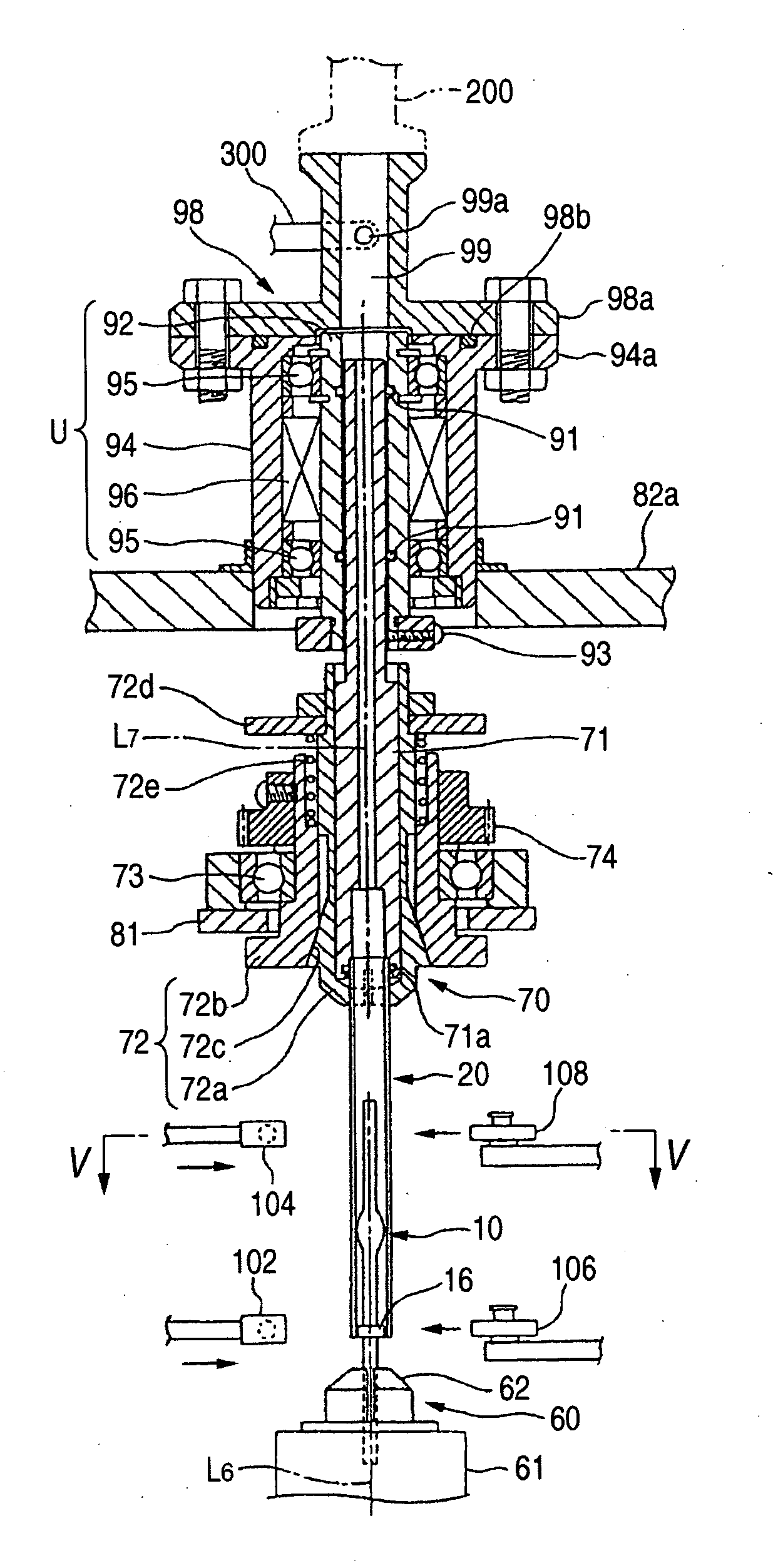
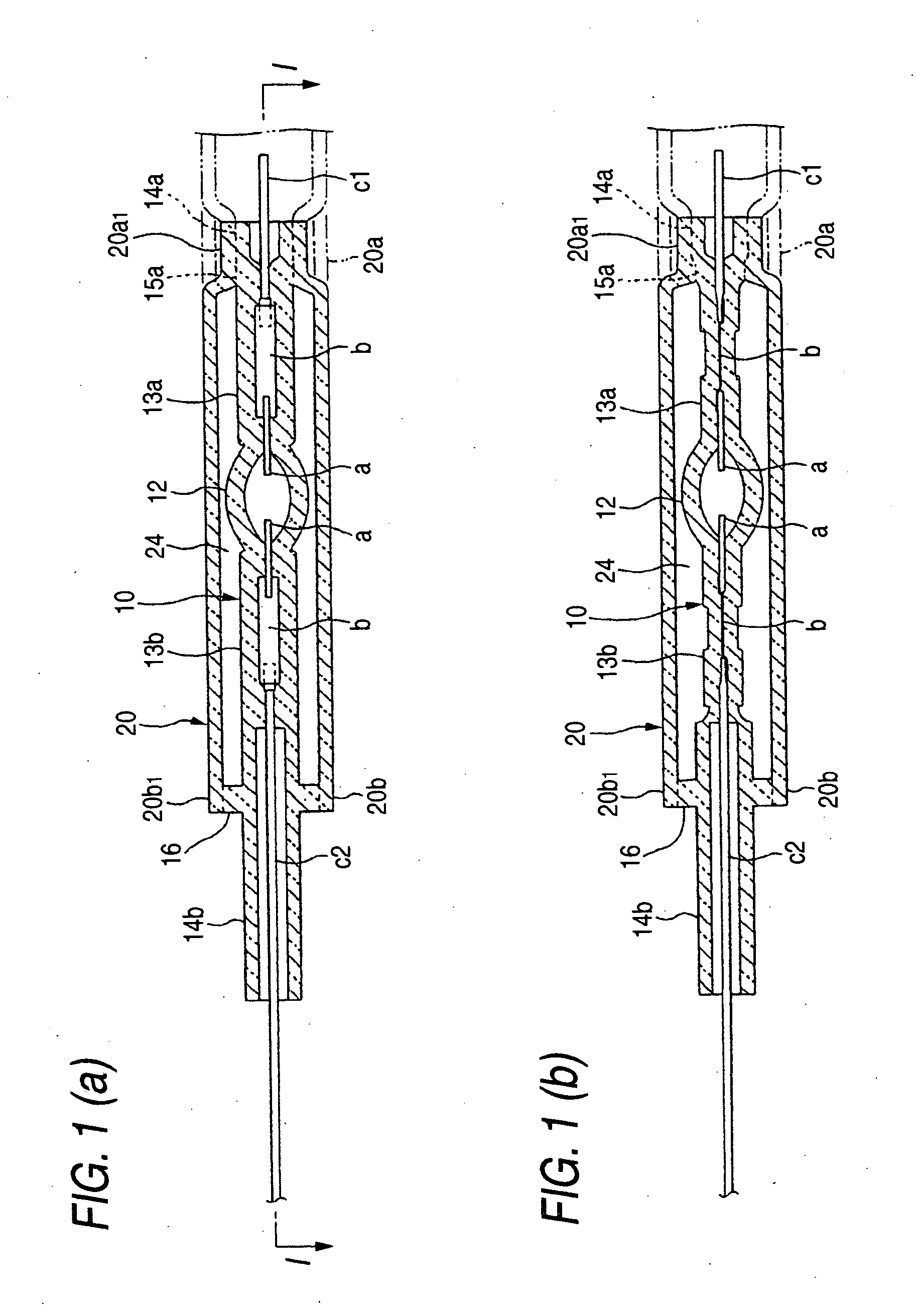
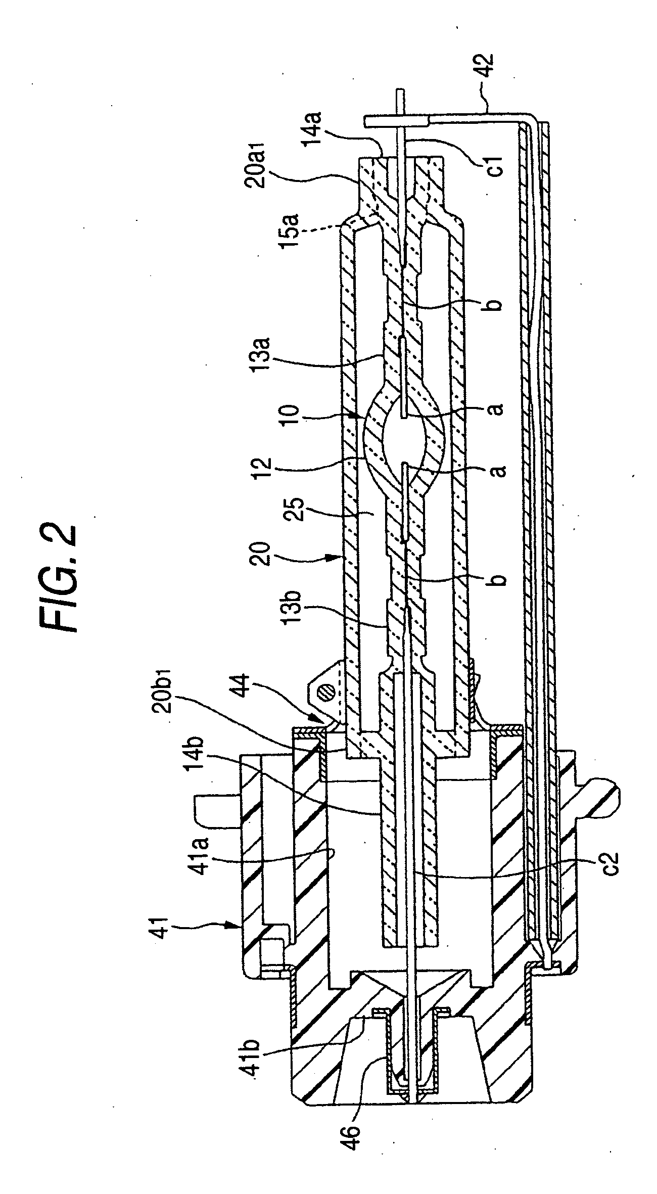
[0061] FIGS. 1 to 6 show an exemplary, non-limiting method and apparatus for welding a shroud glass tube in an arc tube for a discharge lamp. FIG. 1 shows an arc tube welded according to the example of the method of welding a shroud glass tube in accordance with the invention, (a) being a longitudinal sectional view showing the arc tube and (b) being a longitudinal sectional view in an orthogonal position to the section shown in (a) of the arc tube (a sectional view taken along a line I-I in FIG. 1(a)). FIG. 2 is a longitudinal sectional view showing a discharge lamp device applying the arc tube, FIG. 3 is a side view showing a whole apparatus for welding a shroud glass tube to an arc tube body, a part of the apparatus being illustrated in a section, and FIG. 4 is an enlarged sectional view showing the main part of the welding apparatus (a sectional view taken along a line IV-IV in FIG. 3).

[0062]FIG....


PUM

PropertyMeasurementUnit
pressureaaaaaaaaaa
pressureaaaaaaaaaa
pressureaaaaaaaaaa

Abstract

A method of secondarily welding one end of a shroud glass tube covering an arc tube body having a discharge emitting portion, having the other end welded primarily to one of the arc tube body ends, to the other end side of the arc tube body, while discharging air from, and introducing an inactive gas into, the tube through the opening end of the glass tube to hold a negative pressure. Heating and melting from a side is carried out. The opening end of the glass tube is connected to a piping passage component for discharging air and introducing an inactive gas through a rotatable magnetic fluid seal unit. Secondary welding is carried out with the rotation of the glass tube around an axis. The glass tube rotated with respect to secondary side heater is uniformly heated, molten and softened circumferentially, and welded along the arc tube body outer periphery.

Description

[0001] The present invention claims foreign priority under 35 USC 119 based on Japanese patent application 2004-141970, the contents of which are incorporated herein by reference in their entirety. Further, this priority claim is being made concurrently with the filing of this patent application. BACKGROUND [0002] 1. Technical Field [0003] The present invention relates to a method and apparatus for manufacturing an arc tube for a discharge lamp in which a cylindrical shroud glass tube is welded integrally with the outer periphery of an arc tube body having a discharge emitting portion and an inactive gas space regulated to have a negative pressure is formed around the arc tube body, and more particularly to a method and apparatus for welding a shroud glass tube in an arc tube for a discharge lamp in which after a primary welding step of primarily welding one end side of the shroud glass tube to one end side of an arc tube body inserted and provided on a inside, the other end side of...

Claims


Application Information

Patent Timeline
Patent Type & Authority Applications(United States)
IPC IPC(8): H01J9/00H01J9/20H01J9/24H01J9/26H01J9/34H01J9/40
CPCH01J9/266
Inventor HIRATA, MASAYASUKUBOTA, HIROMIMISONOU, SHINYA
Owner KOITO MFG CO LTD
Why Eureka
Try Eureka