Method and apparatus to control hydraulic pressure in an electrically variable transmission

a technology of electrically variable transmission and hydraulic pressure, which is applied in fluid pressure control, instrumentation, and gearing, etc., can solve the problems of hydraulic power loss, difference between actual hydraulic pressure and required hydraulic pressure to meet the torque capacity,

Inactive Publication Date: 2005-11-17
GM GLOBAL TECH OPERATIONS LLC
View PDF3 Cites 163 Cited by
  • Summary
  • Abstract
  • Description
  • Claims
  • Application Information

AI Technical Summary

Problems solved by technology

The difference between actual hydraulic pressure and required hydraulic pressure to meet the required torque capacity represents hydraulic power loss.

Method used


Image

  • Method and apparatus to control hydraulic pressure in an electrically variable transmission
  • Method and apparatus to control hydraulic pressure in an electrically variable transmission
  • Method and apparatus to control hydraulic pressure in an electrically variable transmission

Examples


Embodiment Construction

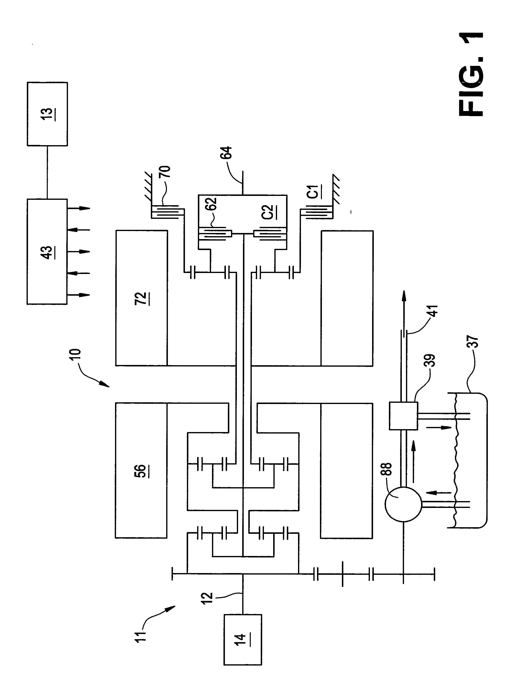
[0013] Referring now to the drawings, wherein the showings are for the purpose of illustrating the invention only and not for the purpose of limiting the same, FIG. 1 shows a mechanical hardware schematic representation of an exemplary form of a two-mode, compound-split, electrically variable transmission and engine particularly suited to the implementation of the present invention. The exemplary system preferably includes a powertrain system 11 with an internal combustion engine 14 and electrically variable transmission (EVT) 10, a system controller 43, and a user interface 13.

[0014] The exemplary EVT 10 described hereinafter, including details regarding design and operation, is disclosed in commonly assigned U.S. Pat. No. 5,931,757, the contents of which are incorporated herein by reference. Further details regarding control of the exemplary EVT, including preferred methods for determining engine speed and engine torque and controlling engine speed may be found in commonly assign...


PUM


Abstract

A method and apparatus to control an electrically variable transmission, by dynamically controlling system main hydraulic clutch pressures, based upon required clutch capacity, as determined by output load of the transmission. Included is a method to regulate hydraulic clutch pressure in an electrically variable transmission equipped with at least one clutch. This comprises monitoring magnitude of slippage of the clutches and controlling hydraulic boost pressure based upon the magnitude of clutch slippage. Controlling hydraulic boost pressure based upon the magnitude of clutch slippage comprises monitoring operator inputs, determining a requested operator torque command, and determining a required main boost pressure. The main boost pressure is based upon the requested operator torque command, the monitored operator inputs, parameters of the EVT and clutches. Commanded main boost pressure is then determined based upon the determined required main boost pressure.

Description

TECHNICAL FIELD [0001] This invention pertains generally to control of an electrically variable transmission for a powertrain, and more specifically to control of hydraulic clutch pressure of the electrically variable transmission for the powertrain. BACKGROUND OF THE INVENTION [0002] Powertrain systems for use in vehicles are expected to operate over a wide range of speed and load conditions. One type of powertrain system includes an electrically variable transmission (EVT) which provides for continuously variable speed ratios by combining features from both series and parallel hybrid powertrain architectures. EVTs are operable with a direct mechanical path between an internal combustion engine and a final drive unit thus enabling high transmission efficiency and application of lower cost and less massive motor hardware. EVTs are also operable with engine operation mechanically independent from the final drive or in various mechanical / electrical split contributions thereby enabling...

Claims


Application Information

Patent Timeline
Patent Type & Authority Applications(United States)
IPC IPC(8): B60K6/365B60K6/445F16D48/06F16H3/72F16H61/50G05D1/02G05D16/20G06F19/00
CPCB60K6/365Y02T10/6239F16D48/066F16D2500/1027F16D2500/1066F16D2500/1087F16D2500/30406F16D2500/31426F16D2500/3144F16D2500/3166F16D2500/70406F16D2500/70426F16H3/728F16H61/0021F16H2037/102F16H2037/104F16H2200/2035F16H2342/044G05D1/024G05D1/027G05D1/0272G05D1/0278G05D16/2066B60K6/445Y02T10/62
Inventor HSIEH, TUNG-MINGHUBBARD, GREGORY A.FOSTER, MICHAEL D.
Owner GM GLOBAL TECH OPERATIONS LLC
Why Eureka
Try Eureka