Electronic card encoder

a technology of encoders and encoders, applied in the field of encoders of electronic cards, can solve the problems of increasing the complexity of the structure, unable to erase and re-encode cards, and common user errors, so as to reduce the likelihood of encoding errors, reliably encode key cards, and keep the encoder structure compact and inexpensive

Inactive Publication Date: 2005-11-24
COMPIZED SECURITY SYST
View PDF49 Cites 31 Cited by
  • Summary
  • Abstract
  • Description
  • Claims
  • Application Information

AI Technical Summary

Benefits of technology

[0009] In one embodiment, the slot is illuminated to guide the user through the encoding process. For example, the slot may be steadily illuminated in a first color to indicate that the encoder is ready to accept a card for encoding, flash in the first color after the card is inserted to indicate that the card is ready to be removed and verified, and be illuminated in a second color

Problems solved by technology

The manual encoding process for this type of structure, however, makes user error common.
This improper code location and format makes it impossible to erase and re-encode the card because the read head cannot locate a code that is does not start and stop in the required zone.
Further, the manual encoding structure requires two heads (i.e., a record

Method used


Image

  • Electronic card encoder
  • Electronic card encoder
  • Electronic card encoder

Examples


Embodiment Construction

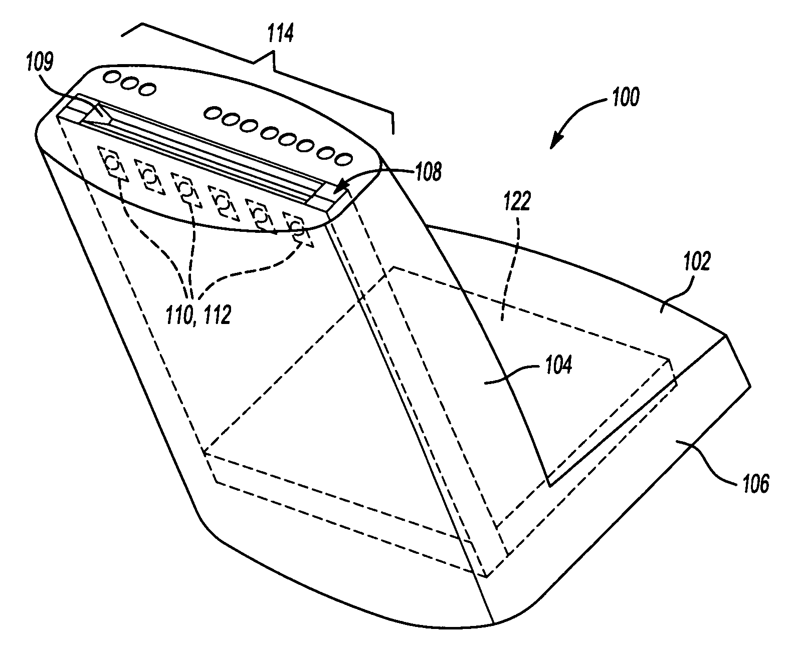
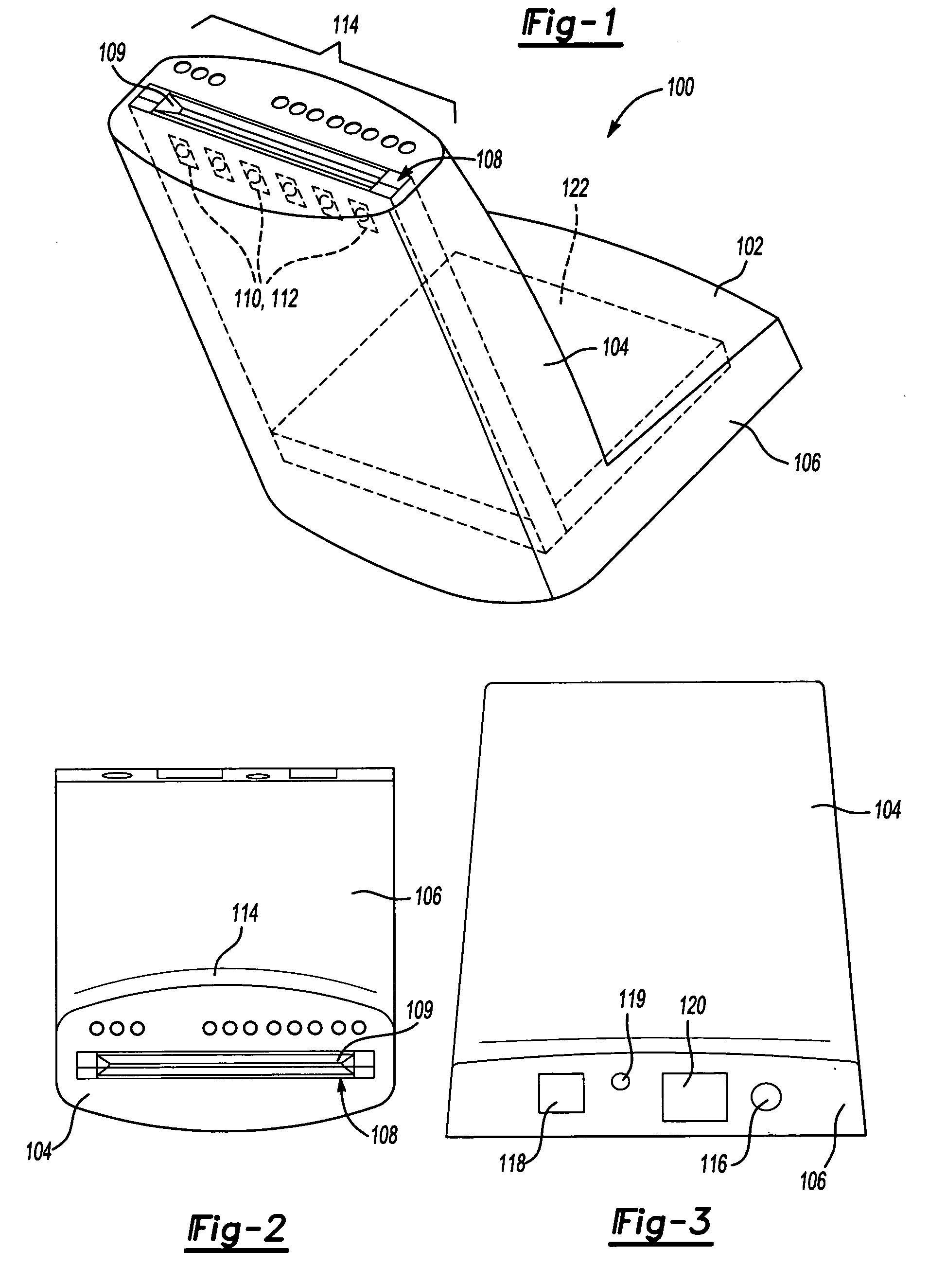
[0018]FIGS. 1 through 3 illustrate a key encoder 100 according to one embodiment of the invention as seen from the outside of the encoder 100. Referring to FIG. 1, the encoder 100 includes a generally L-shaped housing 102 with a card insertion portion 104 and a base portion 106. In one embodiment, the angle between the card insertion portion 104 and the base portion 106 is around 100 degrees (i.e., 10 degrees off from perpendicular). The angled housing, in conjunction with the compact configuration of the encoder's inner components (described in greater detail below) minimizes the amount of desk space that the key encoder 100 occupies.

[0019]FIG. 2 is a representative top plan view of the key encoder 100 of FIG. 1 to show the card insertion portion 104 in more detail. The card insertion portion 104 includes a slot portion 108 having a slot 109 that accommodates a standard key card. The slot 109 preferably is slightly larger than the key card so that the card can be inserted easily i...


PUM


Abstract

A key card encoder incorporates a plunger that is pushed downward as the card is manually inserted into a slot in the encoder and a potentiometer whose value changes based on the plunger position to indicate the card's position at all times. As the card is inserted into the slot, a head encodes a magnetic strip on the card as the card is inserted into the slot, while the head verifies the code in the reverse direction as the card is withdrawn from the slot. The slot is illuminated in different colors and flashing patterns to guide the user through the encoding process and notify the user if there is an encoding error.

Description

TECHNICAL FIELD [0001] The present invention relates to electronic card encoders. BACKGROUND OF THE INVENTION [0002] Electronic key card encoders are often used to produce customized electronic key cards at a point of transaction, such as at a hotel desk. Generally, key encoders carry out an encoding function and a readback function to ensure that the key is properly encoded. As is known in the art, key cards have a magnetic strip that is encoded by the key encoder with a particular unique code. To ensure that the code will be read back properly when it is inserted into a lock, the code must be encoded in a specific zone on the magnetic strip. Thus, key card encoders must be designed so that the location of the card being encoded is known at all times during the encoding and card reading process. [0003] Currently, there are two types of key encoders in common use. One encoder structure is a narrow, rectangular structure having a slot along its length. A gate detects when the edge of...

Claims


Application Information

Patent Timeline
IPC IPC(8): G06K1/12G06K7/00G06K13/067G06K13/08G11B5/008
CPCG11B5/00808G06K7/00
Inventor MITCHELL, ERNST KERNKHALIL, MOHAMAD A.
Owner COMPIZED SECURITY SYST
Why Eureka
Try Eureka