Device and procedure for twisting a coil into perforations of flat components

Inactive Publication Date: 2005-11-24
KUGLER WOMAKO
View PDF10 Cites 2 Cited by
  • Summary
  • Abstract
  • Description
  • Claims
  • Application Information

AI Technical Summary

Benefits of technology

[0015] The invention allows for the use of coils that are precut to a desired length. Thereby the stopping device that is provided by the invention assures that only one coil is handled at a time and twisted into the perforations of the stack of flat components, that is positioned on the outlet side of the machine. This is of particular advantage when using plastic coils. Thus the invention allows a synchronized twisting of coils and is especially suited for a fully automated facility. Therefore less labour is needed and the invention thus leads to an increased production.
[0027] In another preferred model the drive features in addition to the first cylinder at least a second cylinder, on whose casing the coil can be put in position as well and that is always arranged in a fixed relative position to the first coil, so that the first and second cylinder form a pair of cylinders to grab the coil. The first and second coil should be arranged in parallel to each other. Finally the second cylinder should be formed in the same manner as the first cylinder regarding construction and / or bearing. By arranging a second cylinder that corresponds to the first cylinder the contact with the coil is more stable. In addition such a pair of cylinders forms an advantageous arrangement to grab and support the coil, to stretch it against the notched bearing and subsequently submit it to the desired twisting movement.

Problems solved by technology

This known device is meant for wire coils and is constructed in a relatively complicated way.
However, such a procedure can lead to handling problems, in particular when using plastic coils.

Method used


Image

  • Device and procedure for twisting a coil into perforations of flat components
  • Device and procedure for twisting a coil into perforations of flat components
  • Device and procedure for twisting a coil into perforations of flat components

Examples


Embodiment Construction

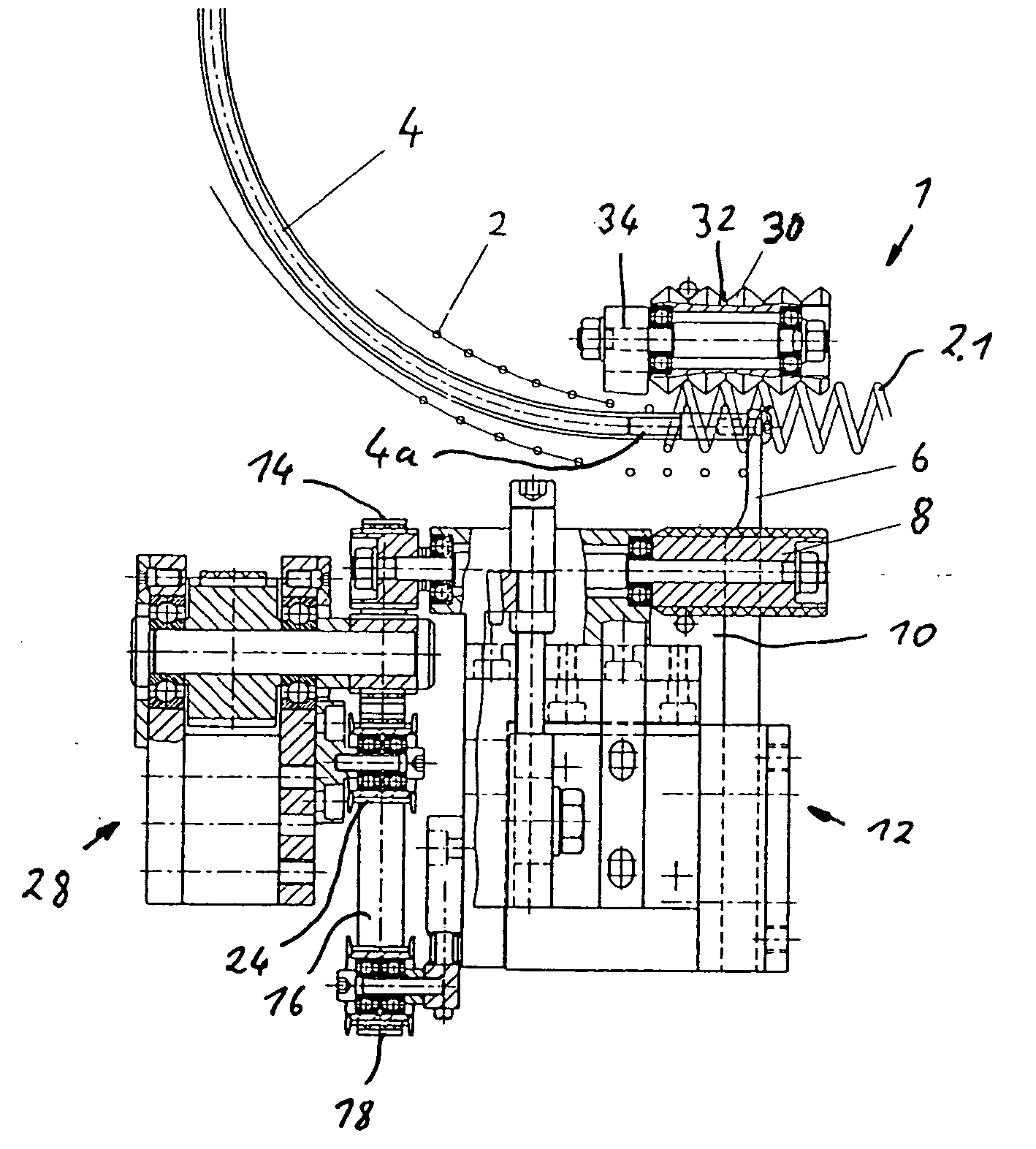
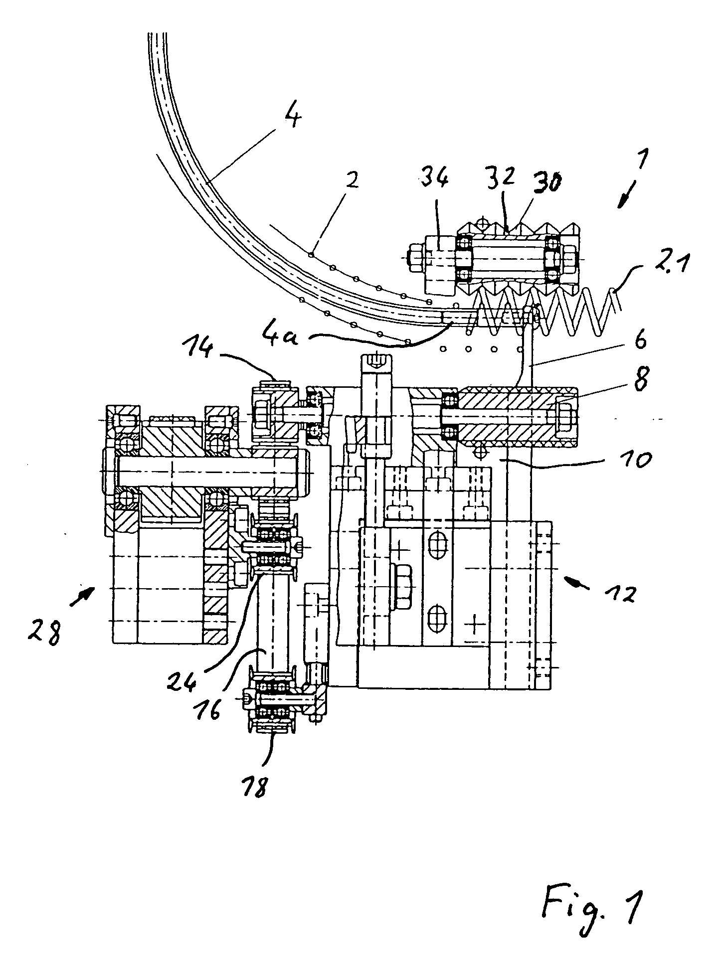
[0033] The device 1 shown in the figures with its essential components serves for twisting a coil 2 that was produced from a thread not shown in an upstream device which is also not shown and features a helix-shape. The coil 2 that can be seen in FIG. 1 only schematically in a cross-section is preferably made of a plastic thread consisting of Thermoplast.

[0034] A flexible feed cable 4, that serves as a transportation device for the coil 2 leads from the above mentioned and not shown device, where the coil 2 got its helix shape, to the pictured device 1. Thus the function of the flexible feed cable 4 is that of a guide way for guiding the coil 2. Typically a hydraulic or pneumatic hose, whose fluid is used for other purposes, is used as feed cable 4. Insofar the feed cable 4 takes on a double function in the shown example. As can be seen in FIG. 1 the coil 2 is slid across the feed cable 4, so that the feed cable 4 reaches across the coil 2 and the coil 2 hangs on the feed cable. Th...


PUM

PropertyMeasurementUnit
Angleaaaaaaaaaa
Thicknessaaaaaaaaaa
Diameteraaaaaaaaaa

Abstract

Described is a device and a procedure to twist a coil into perforations that are provided in the margin sections of flat components, sheets of paper in particular, with a drive that causes the rotation and axial in-feed of the coil, corresponding to the inclination of its helix shape. With a stopping device the coil is inhibited from moving further and a release brings the coil out of contact with the stopping device and into contact with the drive.

Description

CROSS-REFERENCE TO RELATED APPLICATION [0001] This application claims the priority of German Patent Application No. 10 2004 022 246.0-26, filed on May 4, 2004, the subject matter of which is incorporated herein by reference. The disclosure of all U.S. patents and patent applications mentioned below are also incorporated herein by reference. BACKGROUND OF THE INVENTION [0002] The invention pertains to a device for twisting a coil into perforations that are provided in the margin sections of flat components, sheets of paper in particular, with a drive that causes the rotation and axial in-feed of the coil, corresponding to the inclination of its helix shape. Furthermore the invention pertains to a procedure to twist a coil into perforations that are provided in the margin section of flat components, sheets of paper in particular, in particular using a device such as the one mentioned above. [0003] A device such as the one mentioned above is usually part of a semi or fully automatic sy...

Claims


Application Information

Patent Timeline
IPC IPC(8): B21F23/00B21F45/16B42B5/12B65H1/08
CPCB42B5/123
Inventor LEHMANN, HARTMUTVIETH, GUNNAR
Owner KUGLER WOMAKO
Why Eureka
Try Eureka