
Beam forming apparatus and method using interference power estimation in an array antenna system

a technology of array antenna and power estimation, applied in the direction of multi-channel direction-finding systems using radio waves, melt spinning methods, shielding materials, etc., can solve the problems of significant interference in radio transmission, fading dips, and the general only possible effect of adaptive beam forming

Inactive Publication Date: 2005-11-24
SAMSUNG ELECTRONICS CO LTD
View PDF0 Cites 36 Cited by
  • Summary
  • Abstract
  • Description
  • Claims
  • Application Information

AI Technical Summary

Benefits of technology

[0016] It is further another object of the present invention to provide a beam forming apparatus and method capable of reducing implementation complexity and efficiently using spatial diversity in a Time Domain Duplex (TDD) system such as a Time Division Synchronous Code Division Multiple Access (TD-SCDMA).

Problems solved by technology

This becomes a cause of fading dips where received signals substantially disappear, and the fading dip occurs as frequently as a length corresponding to a wavelength.
Another phenomenon that significantly affects radio transmission is interference.
In a cellular radio system, interference is directly related to a requirement of communication capacity.
Therefore, adaptive beam forming can generally only be accomplished after estimation of the spatial channels.
However, its latent faculty is limited by the geometry of an array antenna having a finite spatial resolution.
When a multipath, multiuser scenario is used, the conventional beam forming method cannot be used any longer because it assumes a single-path channel.
Spatial selective channel estimation based on irregular spatial sampling proposed to solve this problem requires considerably complex implementation and cannot provide the advantage of the spatial diversity.

Method used


Image

  • Beam forming apparatus and method using interference power estimation in an array antenna system
  • Beam forming apparatus and method using interference power estimation in an array antenna system
  • Beam forming apparatus and method using interference power estimation in an array antenna system

Examples


Embodiment Construction

[0025] Preferred embodiments of the present invention will now be described in detail with reference to the accompanying drawings. In the following description, a detailed description of known functions and configurations incorporated herein has been omitted for conciseness.

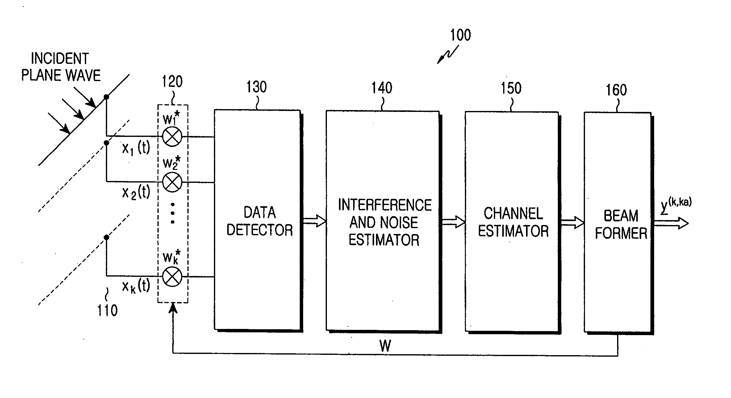
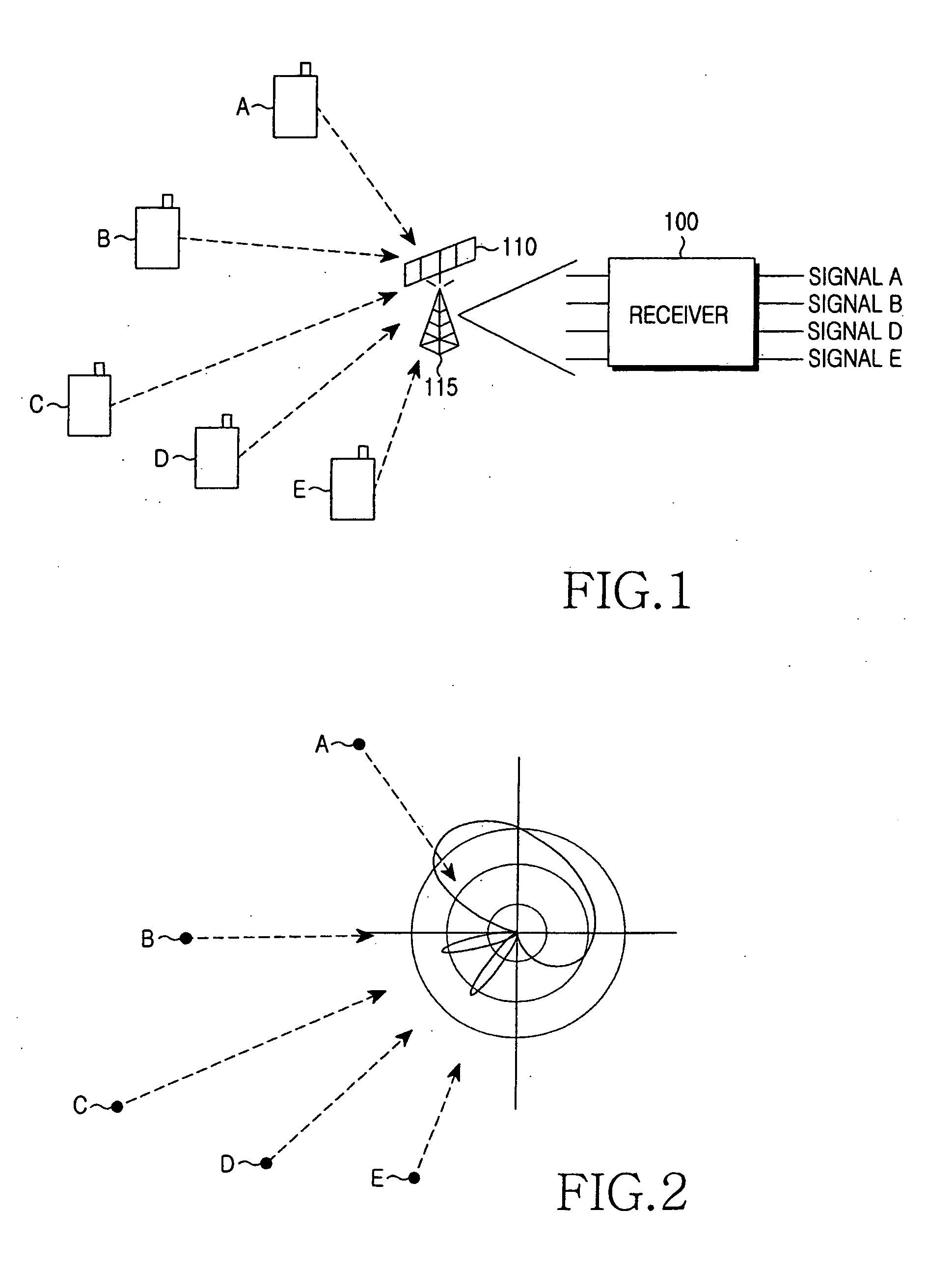
[0026] The present invention described below does not consider DOAs of maximum incident waves that need irregular spatial sampling, in performing beam forming by estimating spatial channels in an antenna diversity system. The irregular spatial sampling requires accurate time measurement and time-varying reconstruction filtering, and is more complex to implement than a regular sampling strategy. Therefore, the present invention pre-calculates a linear system model beginning at regular spatial sampling that uses regular spatial separation for a beam angle, thereby dramatically reducing the complexity of channel estimation.

[0027] For estimation of spatial channels, a reception side requires the arrangement of an a...


PUM

PropertyMeasurementUnit
Densityaaaaaaaaaa
Cell angleaaaaaaaaaa
Efficiencyaaaaaaaaaa

Abstract

An apparatus and method are provided for simply estimating joint channel and Direction-of-Arrival (DOA) to efficiently estimate a channel impulse response associated with a spatially selective transmission channel occurring in a mobile radio channel, and performing efficient beam forming using the simplified joint channel and DOA estimation are provided. A receiver estimates the total interference power using power for each interference signal, estimates a spectral noise density, calculates steering vectors considering predetermined DOAs, and jointly calculates optimal weight vectors for each DOA of each user by applying the interference power and the spectral noise density to the steering vectors. The beam forming reduces implementation complexity of a TDD system such as a TD-SCDMA and increases beam forming efficiency in a mobile environment by efficiently using spatial diversity.

Description

PRIORITY [0001] This application claims the benefit under 35 U.S.C. § 119(a) of an application entitled “Beam Forming Apparatus and Method Using Interference Power Estimation in an Array Antenna System” filed in the Korean Intellectual Property Office on May 24, 2004 and assigned Serial No. 2004-36746, the entire contents of which are incorporated herein by reference. BACKGROUND OF THE INVENTION [0002] 1. Field of the Invention [0003] The present invention relates generally to an array antenna system, and in particular, to an apparatus and method for optimal beam forming for transmitting and receiving high-speed data at high performance. [0004] 2. Description of the Related Art [0005] Reception quality of radio signals is affected by many natural phenomena. One of the natural phenomena is temporal dispersion caused by signals reflected on obstacles in different positions in a propagation path before the signals arrive at a receiver. With the introduction of digital coding in a wirel...

Claims


Application Information

Patent Timeline
IPC IPC(8): G01S3/16G01S3/72G01S3/74H04B7/04H01Q3/00H04B1/00H04B7/08
CPCG01S3/72H04B7/086G01S3/74D01D5/08D01F1/09D01F1/103H05K9/009D10B2401/13D10B2401/16
Inventor KIM, BYOUNG-YUNKIM, SONG-HUNLEE, HYEON-WOOJEONG, KWANG-YUNGLEE, HYE-YOUNGJUNG, PETER
Owner SAMSUNG ELECTRONICS CO LTD
Learn More