Dual band loop antenna

a loop antenna and antenna technology, applied in the direction of loop antennas, electrically long antennas, and antenna adaptation in movable bodies, etc., can solve the problems of affecting the overall performance of the antenna, and reducing the height of the antenna

Inactive Publication Date: 2005-11-24
DELPHI TECH INC
View PDF21 Cites 12 Cited by
  • Summary
  • Abstract
  • Description
  • Claims
  • Application Information

AI Technical Summary

Problems solved by technology

In many circumstances, height of the antenna may not be reduced because antenna performance may be compromised.
The height may be reduced to as little as 65 mm, however, a height reduction less than 65 mm may degrade the overall performance of the antenna.
However, the diameter/width of antenna is undesirably increased to be a

Method used


Image

  • Dual band loop antenna
  • Dual band loop antenna
  • Dual band loop antenna

Examples


Embodiment Construction

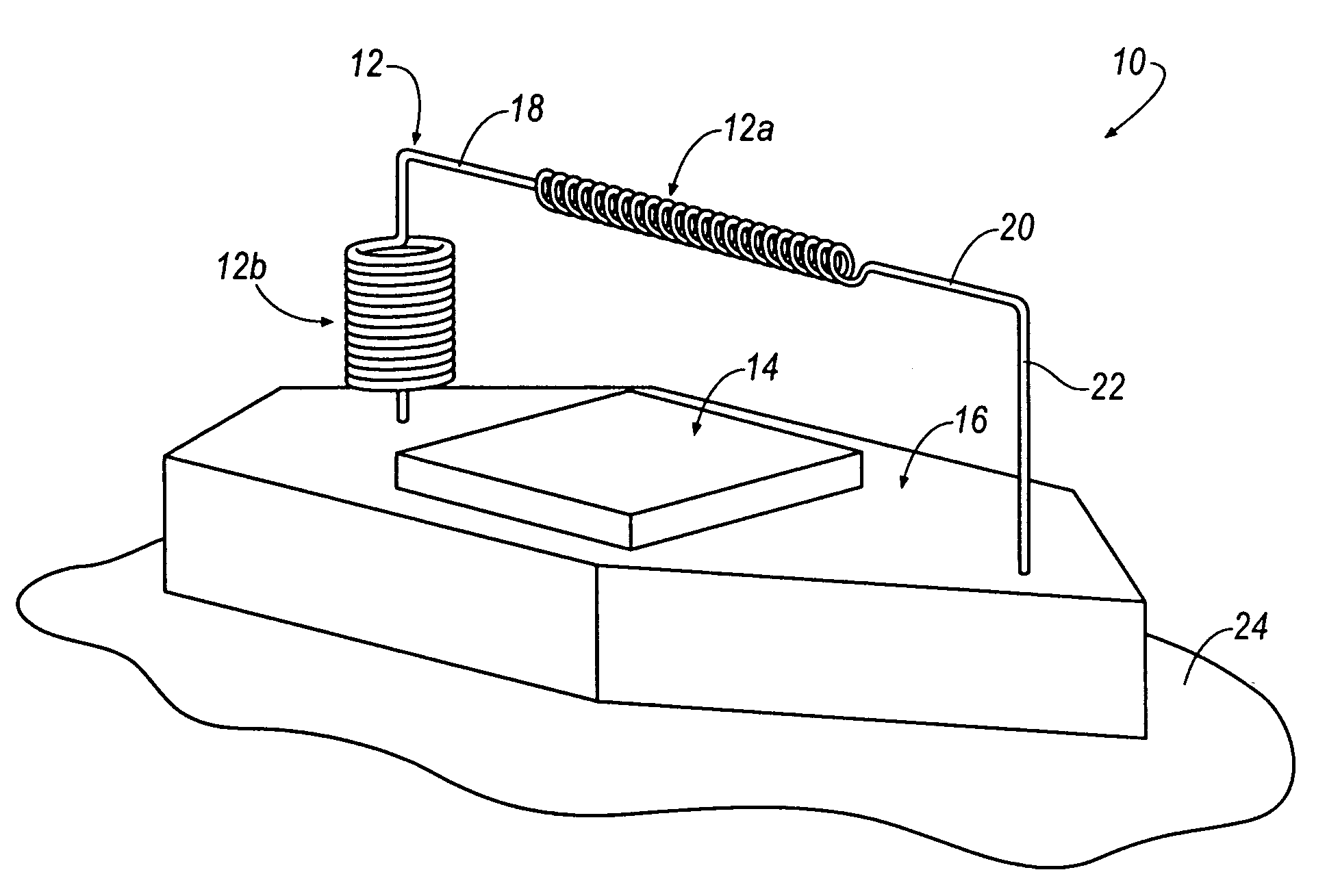
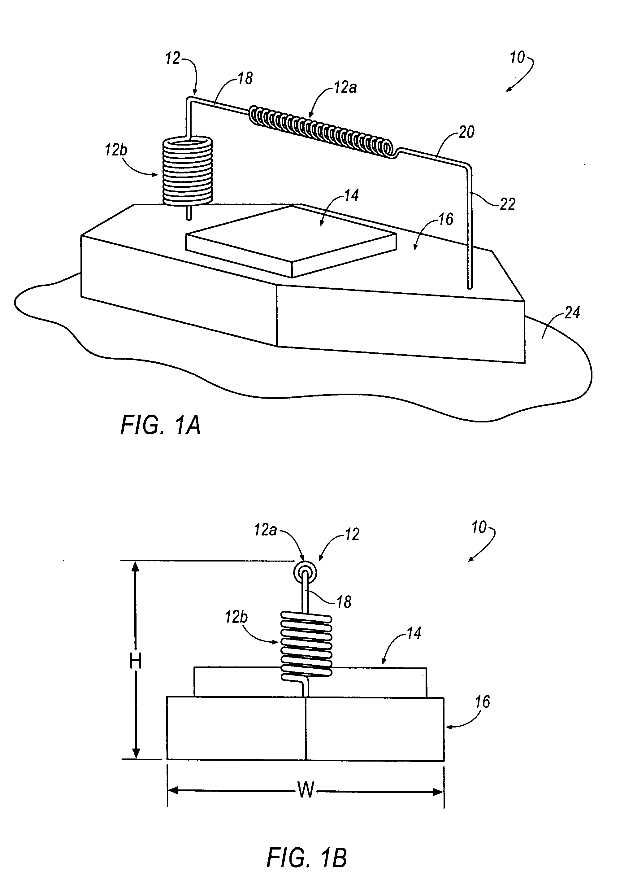
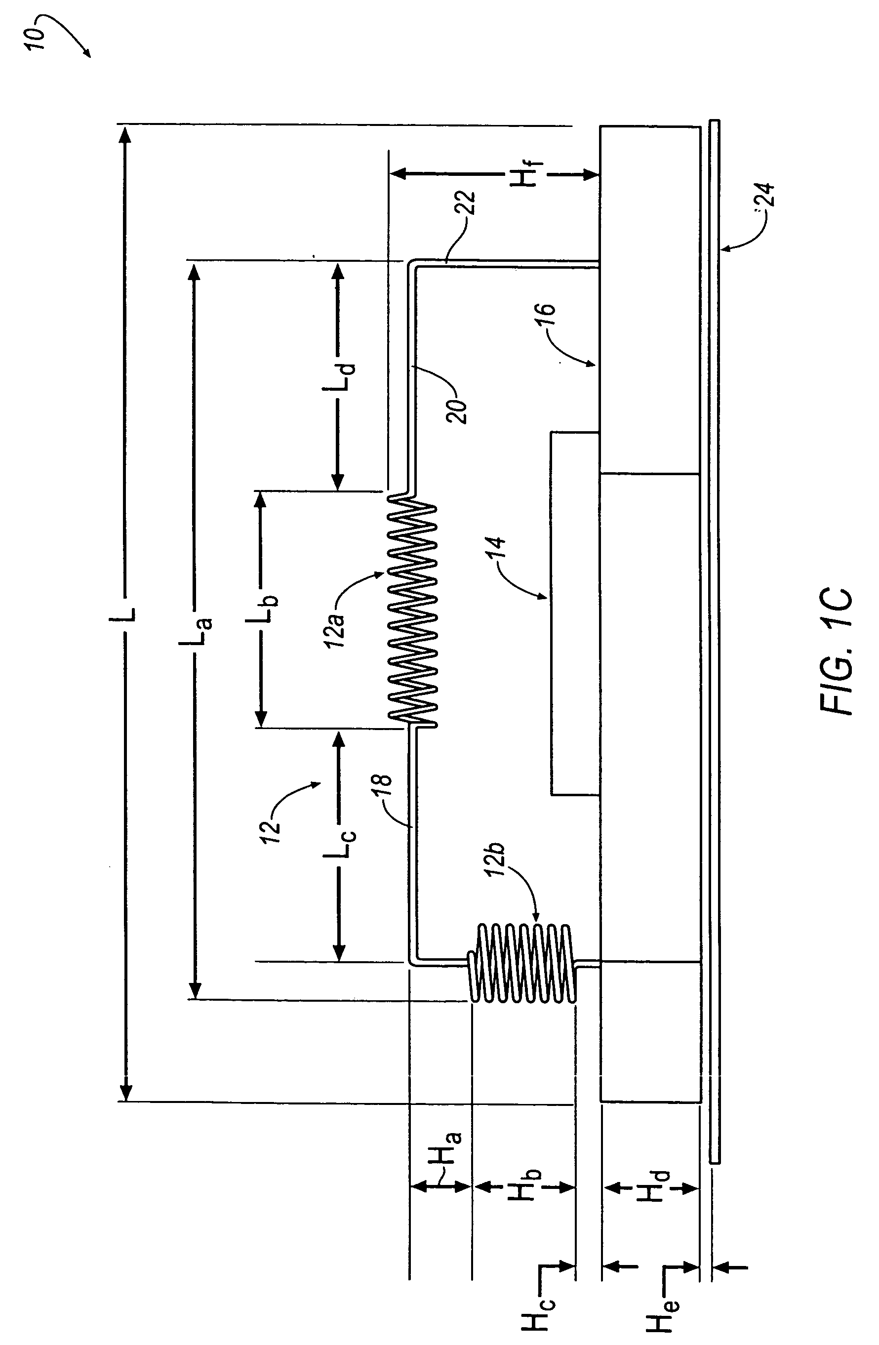
[0015] Referring generally to FIGS. 1A-4, the above described disadvantages are overcome and a number of advantages are realized by a dual band loop antenna assembly, which is seen generally at 10, 100, 200, and 300. Each antenna assembly 10, 100, 200, 300 is a low-profile dual band antenna that accommodates operation between the 824-849 MHz band for AMPS uplink, the 869-894 MHz band for AMPS downlink, the 1850-1910 MHz band for PCS uplink, and the 1930-1990 MHz band for PCS downlink.

[0016] Referring initially to FIGS. 1A-1C, the antenna assembly 10 includes at least one radiating element, such as, for example, a PCS / AMPS wire antenna 12, a patch antenna 14, and associated immediate active circuitry (not shown) within a printed circuit board (PCB) 16. The patch antenna may provide a combinational antenna assembly if global positioning signals (GPS), satellite digital audio radio system (SDARS) signals, or the like, are to be received. Functionally, antennas, such as the patch anten...


PUM


Abstract

An antenna assembly is disclosed. The antenna assembly includes a dual band vertical loop wire antenna extending from a printed circuit board positioned over a ground plane, wherein the wire antenna includes: at least one coiled section, at least one straight wire section, and at least one feeding post section.

Description

TECHNICAL FIELD [0001] The present invention generally relates to antenna assemblies and, more particularly, to a dual band loop antenna. BACKGROUND OF THE INVENTION [0002] Automotive vehicles are commonly equipped with dual-band personal communication systems (PCS) and digital / analog mobile phone service (AMPS) antennas. Such antennas have a height, for example, of at least 70 mm, and are implemented for cellular phone usage. Typically, these antennas are mounted exterior to the vehicle to achieve improved antenna performance and reduced radio frequency (RF) emissions to the inside of the vehicle. In many circumstances, height of the antenna may not be reduced because antenna performance may be compromised. [0003] Due to high efficiency and ease of construction characteristics, helical wire antennas remain the first choice for many cellular antenna designers. For wire antennas, the optimum operation corresponds to λ / 4 wavelength. The height, which is approximately 75-80 mm, is very...

Claims


Application Information

Patent Timeline
IPC IPC(8): H01Q1/32H01Q5/00H01Q5/357H01Q7/00
CPCH01Q1/3275H01Q5/357H01Q7/00
Inventor YEGIN, KORKUTMORRIS, DANIEL G.GHAFARI, ELIAS H.SNOEYINK, RANDALL J.LIVENGOOD, WILLIAM R.
Owner DELPHI TECH INC
Why Eureka
Try Eureka