Digital camera with non-uniform image resolution

a digital camera and resolution technology, applied in the field of digital cameras, can solve the problems of image quality degradation, large data processing power of jpeg and mpeg type compression, etc., and achieve the effects of increasing the resolution of the ball area, increasing the number of pixels, and uniform width

Inactive Publication Date: 2005-11-24
ADAPTIVE IMAGING TECH
View PDF19 Cites 103 Cited by
  • Summary
  • Abstract
  • Description
  • Claims
  • Application Information

AI Technical Summary

Benefits of technology

[0015] A digital camera according to the invention may include a mechanism to sample a linear array at a variable resolution, so that at least some of the scan lines are diluted from processing. Dilution of pixels within a scan line and dilution of scan-lines within the image may be synchronized to define a desirable two-dimensional pixel density of at least one sub-area of the image. The dilution may be controlled by information taken from a binary lookup table that specifies the lines to be acquired and the pixels to be acquired in each line. The dilution may correspond to a pre-determined level of interest in sub-areas of the scene. The contents of the lookup table may correspond to the expected distance between the camera and the scene at any given elevation angle and azimuth. The contents of the lookup table may be at least partially determined by the image contents of preceding images, and may correspond to the results of a video motion detection system. The correspondence of the binary lookup table to the geometry of the scene may be based on a preliminary image analysis of the scene and estimation of distances to objects from their angular size in the field of view. The lookup table may be modified between frames to maintain at least one moving object in the scene under higher resolution.
[0016] The digital camera of the invention may further include multiple linear arrays that are staggered in a generally collinear arrangement to produce an array having a higher number of pixels. Errors in linearity and contiguity of staggering the linear arrays may be compensated by calibration offset in a calibration table.
[0017] The camera of the invention can be used in various applications. For example, it may be used to monitor airport takeoff and landing strips by scanning the strips with the camera, positioned above at least one end of the strip, with the lookup table programmed to cover the generally trapezoidal appearance of the strip in generally uniform resolution. The camera can further be used for automatic optical inspection of a product in a production line. Still further, the camera of the invention may be used as a traffic control digital camera that zooms on at least one of the license plate and driver's head following a prediction of their expected position in the field of view. The camera of the invention may be used to acquire a video image of a sports speed contest where competitors are contending in parallel lanes along a straight line, with the lanes imaged as parallel vertical stripes having uniform width and a linear vertical scale. It may be used in a video ball tracking system where the resolution of the ball area increases as the distance from the camera to the ball increases. The camera may further be used in an illumination system for a revolving mirror scanning camera, wherein a narrow vertical beam of light is synchronized with the direction of the scanning line. The vertical beam of light may be generated by a linear light source, a lens, and a revolving mirror that is mechanically linked to a revolving mirror of the camera. The invention may be used to provide a light reflector having a grid of at least three corner mirror reflectors and means for optically blocking at least one of said corner reflectors to create a variety of identifiable reflection patterns. The digital camera of the invention may be used to provide a visual surveillance system for delivery of high resolution images of a partial feature of an object. In such surveillance systems the digital camera may be used to repeatedly image a field of view at a first resolution. An image processing system may then be used to recognize objects in the images, and a context analysis system my be provided for predicting where, in the geometrical context of the objects, is the expected position of partial features. A programmable lookup table may then be programmed to assign high resolution at the expected position of those features in the forthcoming image. The objects recognized by such surveillance system may be human bodies and the features may be faces. Alternatively, the objects recognized may be vehicles and the features may be license plates. The camera of the invention may further be used to provide a system for assisting a user to visually find items in a field of view. In such embodiments, the system may further include, in addition to the camera, a programmable visual pointing device installed in the vicinity of the camera and a pattern recognition system capable of recognizing the appearance of the items in the image of the camera. A pointing controller may be provided for programming the visual pointing device to visually mark the recognized items. The items may be, e.g., components of an assembly and the field of view is an assembly in front of the user. The items may alternatively be printed words, and the field of view a printed document in front of the user. In this respect, the camera and the pointer may be packaged within the head of a desk lamp.

Problems solved by technology

With either of these techniques, the image deteriorates in quality as one adds compression.
In any event, JPEG and MPEG type compression requires substantial data processing power.

Method used


Image

  • Digital camera with non-uniform image resolution
  • Digital camera with non-uniform image resolution
  • Digital camera with non-uniform image resolution

Examples


Embodiment Construction

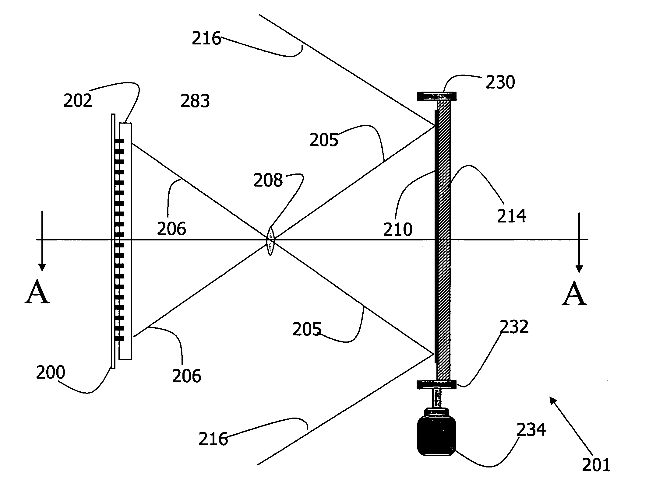
[0074] Reference will now be made in detail to the preferred embodiments of the present invention, examples of which are illustrated in the accompanying drawings. For clarity, corresponding features are consistently labeled across the various views of the invention provided in the figures.

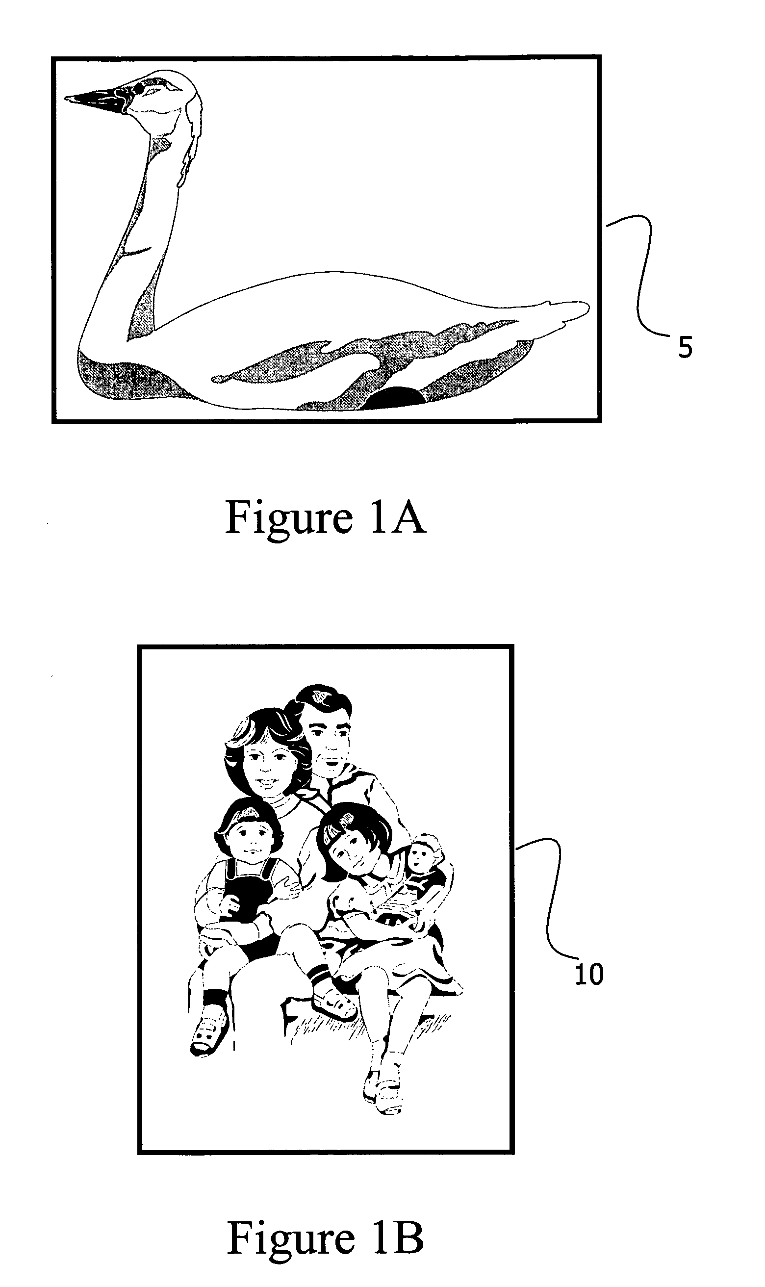
[0075] Turning to FIG. 1A. A rectangular scene with proportions of 3:4 is shown. The frame 5 is in horizontal or landscape orientation. This is the common proportion of images, and many cameras are built to provide a frame in this proportion. FIG. 2 shows another rectangular scene, this time with proportions of 4:3. The frame 10 is in vertical or portrait orientation. The choice between portrait and landscape is the only choice of field shape that is typically available using a conventional camera.

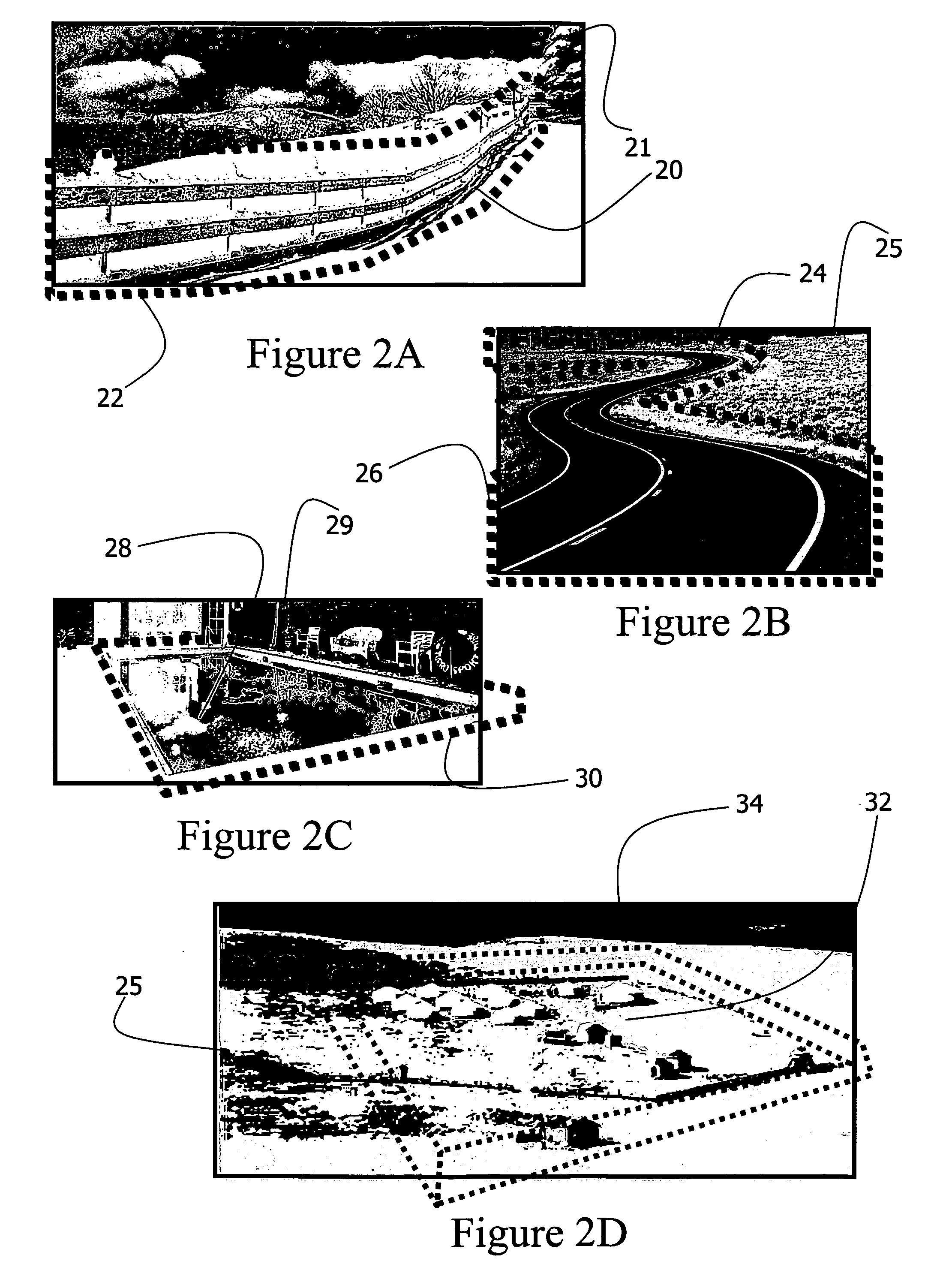
[0076] Turning now to FIG. 2A, a scene comprising a fence 20 is shown. The fence 20 takes a relatively small portion of frame 21. If the fence 20 were the only image of interest in the frame 21 (such as...


PUM


Abstract

The invention provides a system for isolating digital data representative of portions of a field of view. The system, which may be provided in the form of a digital camera, includes an array of sensor cells adapted to provide digital representations corresponding to at least a portion of the field of view, and a selector adapted to isolate a non-uniformly distributed subset of the digital representations provided by the array. The isolation may be performed based upon a set of values programmed in a programmable lookup table. A buffer is provided for holding the isolated digital representations.

Description

PRIORITY CLAIM [0001] This application claims priority to U.S. Patent Application No. 60 / 521,471 filed May 1, 2004, the entire disclosure of which is incorporated herein by reference. This application further claims priority to U.S. Patent Application Ser. No. 60 / 522,743, filed Nov. 4, 2004, which is hereby incorporated by reference in its entirety.FIELD OF THE INVENTION [0002] The present invention relates to the field of digital imaging, and in particular to digital cameras for capturing a scene in a given field of view. BACKGROUND OF THE INVENTION [0003] A camera is a device that captures an image or scene by optically projecting it onto a sensing device in a focal plane. A film camera exposes a light-sensitive film placed on the focal plane to the projected image for a period of time in order to record the image. Over the years, both still and moving film cameras have used a variety of film sizes and aspect ratios. Although in the early days of cameras, film was often cut to siz...

Claims


Application Information

Patent Timeline
Patent Type & Authority Applications(United States)
IPC IPC(8): H04N5/225
CPCH04N3/1562H04N5/374H04N5/3456H04N5/335H04N25/00H04N25/443H04N25/445H04N25/61H04N25/76
Inventor JACOB, ELIEZERPOMERANTZ, ITZHAKMILLER, GIDEON
Owner ADAPTIVE IMAGING TECH
Why Eureka
Try Eureka