Projection display

a projection display and display technology, applied in waveguides, lighting and heating apparatus, instruments, etc., can solve the problems of short life span of lamps of several thousands of hours at most, degraded light condensation efficiency, etc., and achieve the effect of long life span

Inactive Publication Date: 2005-11-24
SAMSUNG ELECTRONICS CO LTD
View PDF12 Cites 31 Cited by
  • Summary
  • Abstract
  • Description
  • Claims
  • Application Information

AI Technical Summary

Benefits of technology

[0007] The present general inventive concept provides a projection disp...

Problems solved by technology

However, these lamps have short life spans of several thousands of hours at most.
In this case, lig...

Method used


Image

  • Projection display
  • Projection display
  • Projection display

Examples


Embodiment Construction

[0027] Reference will now be made in detail to the embodiments of the present general inventive concept, examples of which are illustrated in the accompanying drawings, wherein like reference numerals refer to the like elements throughout. The embodiments are described below in order to explain the present general inventive concept while referring to the figures.

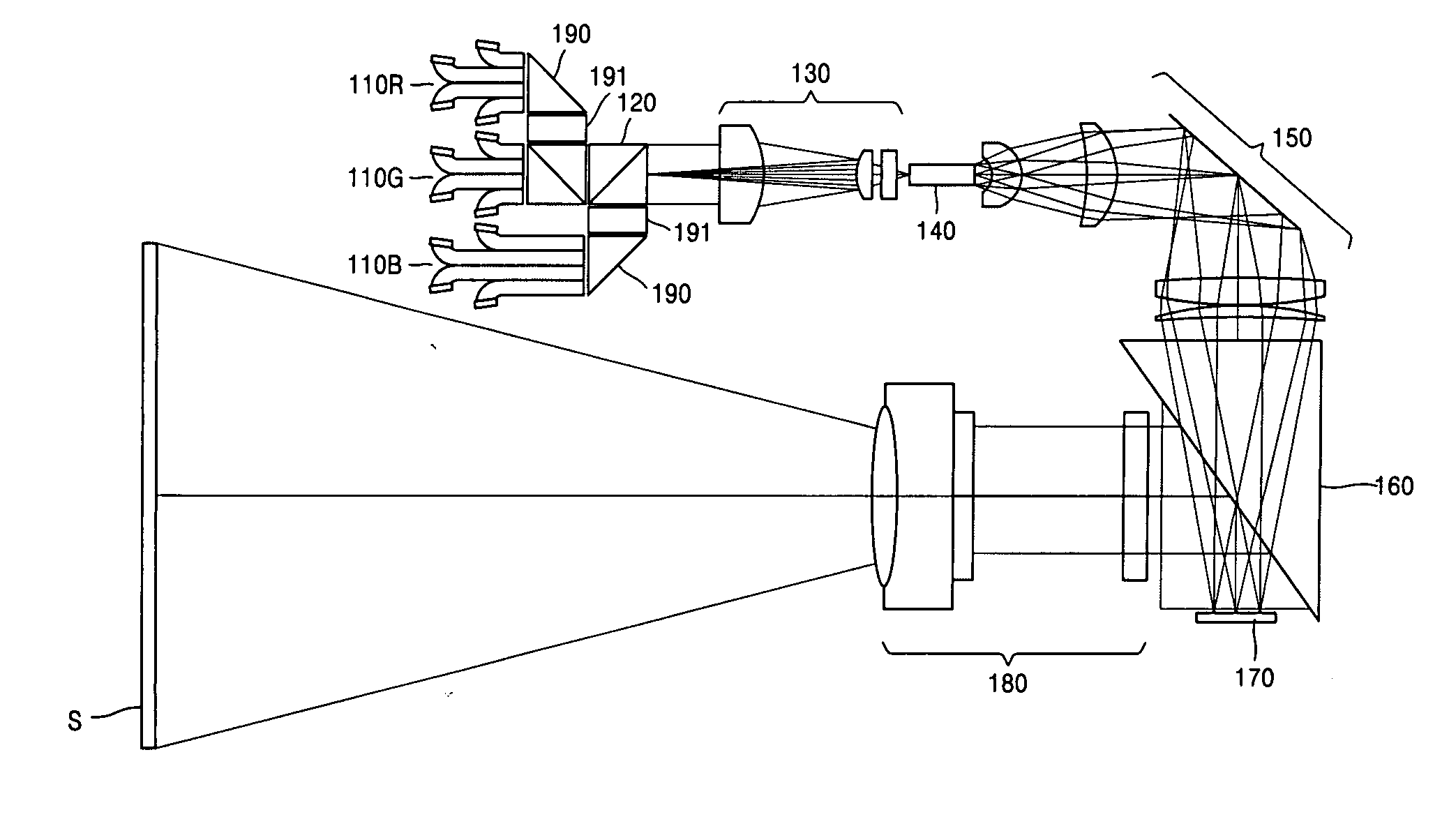
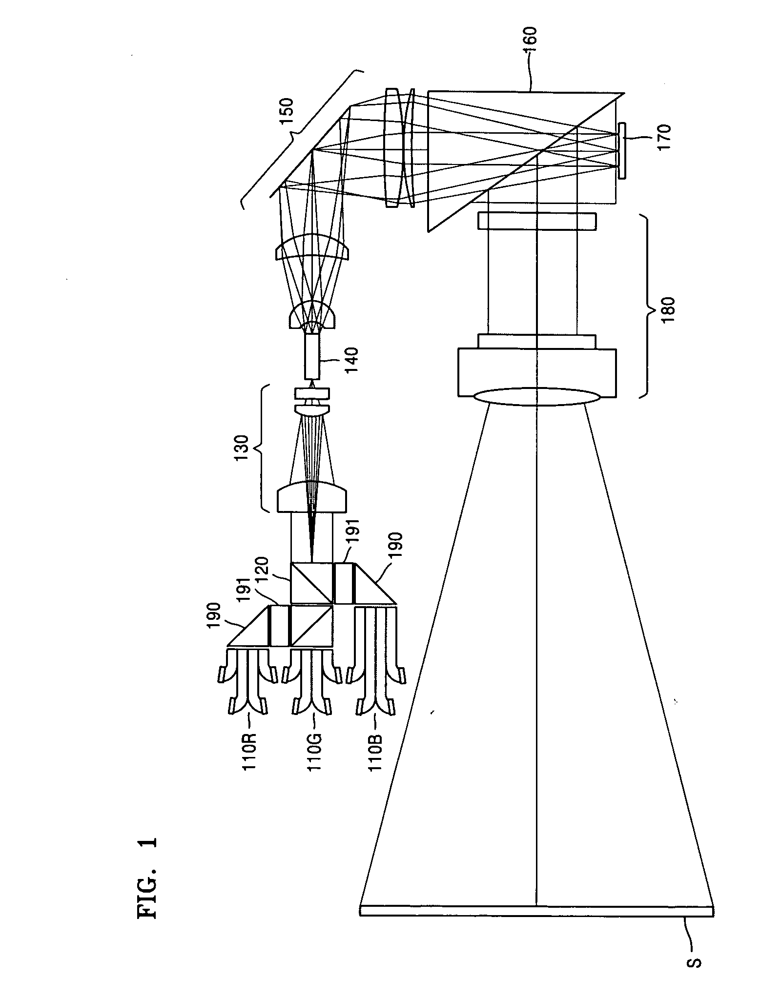
[0028] Referring to FIG. 1, a projection display according to an embodiment of the present general inventive concept includes first through third light source units 110R, 110G, and 110B, to emit first through third light beams R, G, and B, respectively, a light path combining unit 120, to combine light paths of the first through third light beams R, G, and B, an optical modulator 170 to sequentially modulate the first through third light beams R, G, and B according to image information, and a projection lens unit 180, to magnify and project modulated first through third light beams R, G, and B onto a screen S. This projecti...


PUM


Abstract

A projection display including first through third light source units to radiate first through third light beams having different colors, respectively, a light path combining unit to combine paths of the first through third light beams, an optical modulator to sequentially modulate the first through third light beams according to image information, and a projection lens unit to magnify and project the modulated light beams onto a screen. The light path combining unit includes first and second prisms. The first prism includes first and second incidence surfaces, through which the first and second light beams are incident, respectively, a first emission surface, and a first selective reflection surface to transmit the second light beam toward the first emission surface. The second prism includes a third incidence surface, through which the third light beam is incident, a fourth incidence surface, through which the first and second light beams emitted through the first emission surface are incident, a second emission surface, and a second selective reflection surface to reflect the third light beam and to transmit the first and second light beams toward the second emission surface.

Description

CROSS-REFERENCE TO RELATED APPLICATIONS [0001] This application claims the benefit of Korean Patent Application No. 10-2004-0036638, filed on May 22, 2004, in the Korean Intellectual Property Office, the disclosure of which is incorporated herein in its entirety by reference. BACKGROUND OF THE INVENTION [0002] 1. Field of the Invention [0003] The present general inventive concept relates to a projection display which modulates a plurality of light beams having different colors so as to be suitable for image information and magnifies and projects the modulated light beams to display a color image. [0004] 2. Description of the Related Art [0005] Projection displays include optical modulators for modulating light to be suitable for image information and illumination units for illuminating the optical modulators. A metal halide lamp, a super-high voltage mercury lamp, or the like has been used in an illuminating unit. However, these lamps have short life spans of several thousands of ho...

Claims


Application Information

Patent Timeline
IPC IPC(8): G02B27/18G03B21/00G03B21/14G03B21/20H04N9/31
CPCH04N9/3114H04N9/3155H04N9/3197Y10S385/901G03B21/2033G03B21/208G03B21/2013G03B21/14
Inventor LEE, YOUNG-CHOLLEE, WON-YONGSOKOLOV, KIRILLLEE, KYE-HOON
Owner SAMSUNG ELECTRONICS CO LTD
Why Eureka
Try Eureka