
Binocular optical treatment for presbyopia

a binocular optical and presbyopia technology, applied in laser surgery, eye surgery, therapeutic cooling, etc., can solve the problems of not being able to clearly see objects, the ability of crystalline lenses to lose almost all elastic properties, and the inability to focus on objects at near distances, so as to improve the patient's ability to view, and improve the effect of treatment or amelioration of presbyopia

Inactive Publication Date: 2005-11-24
AMO MFG USA INC
View PDF4 Cites 73 Cited by
  • Summary
  • Abstract
  • Description
  • Claims
  • Application Information

AI Technical Summary

Benefits of technology

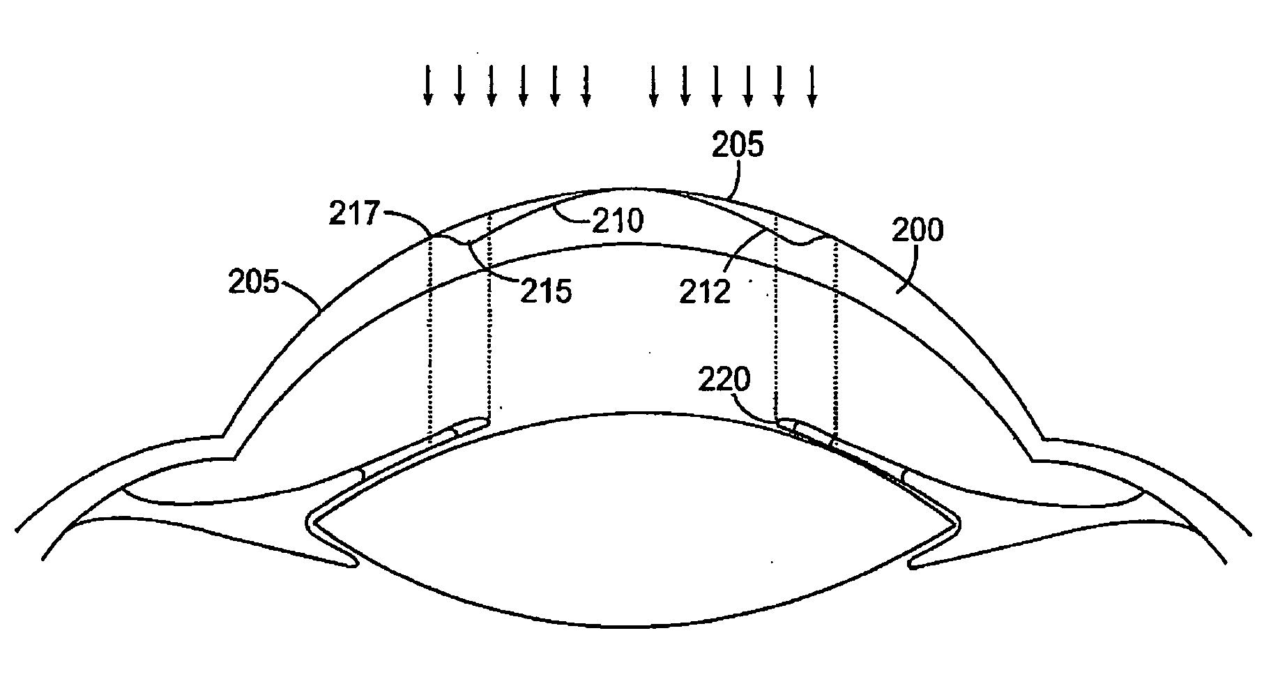
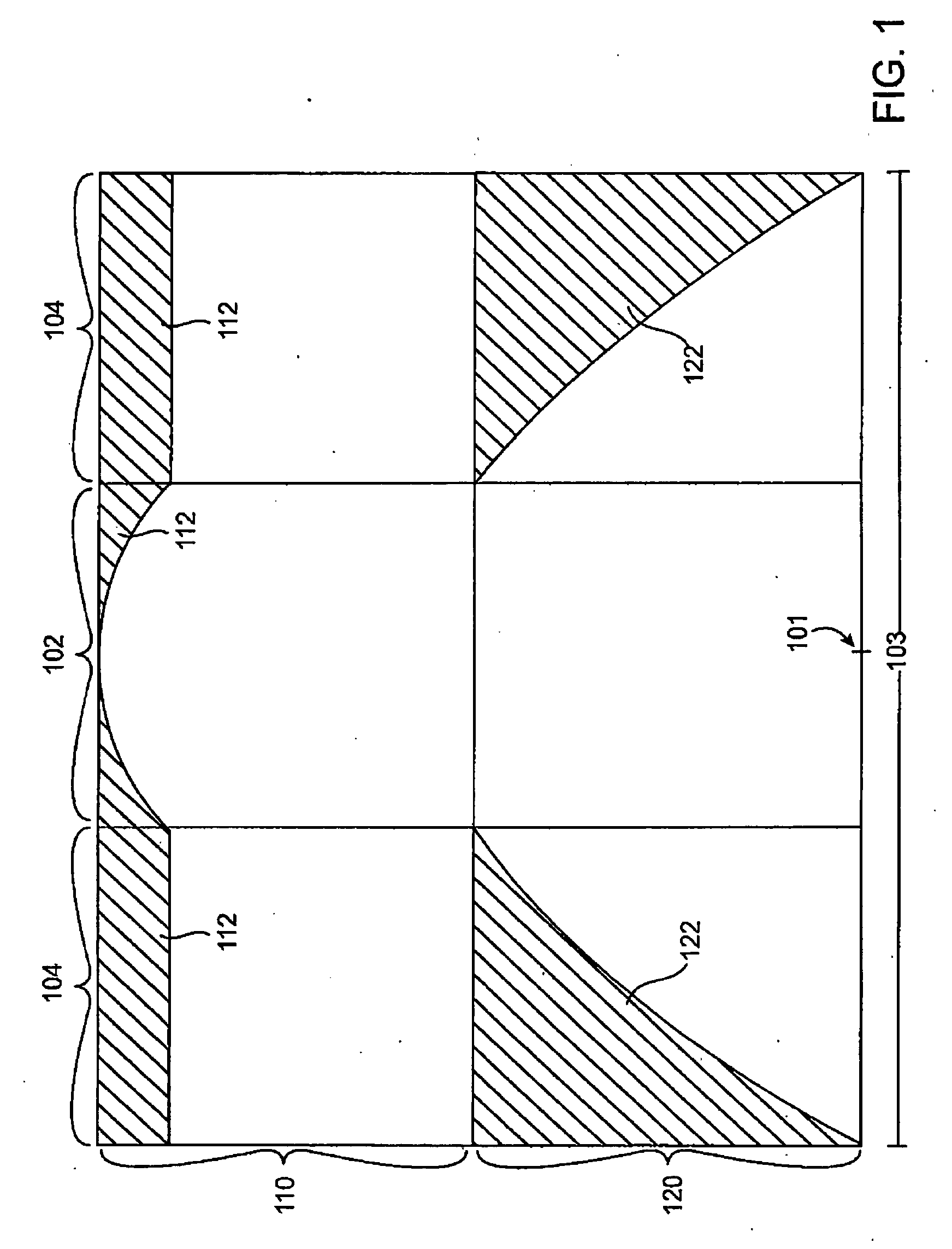
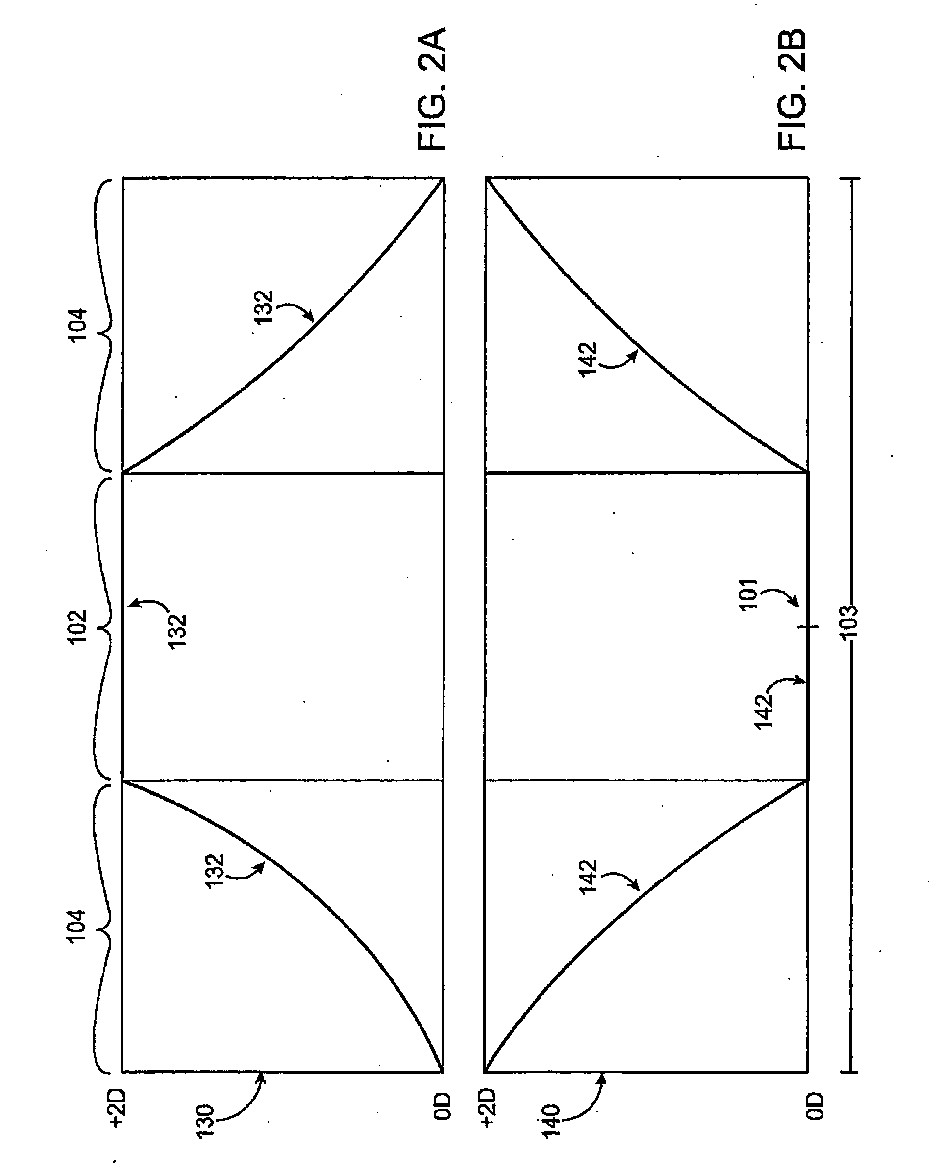
[0010] Systems and methods of the present invention provide for treatment or amelioration of presbyopia. In one aspect of the invention, a method for treating presbyopia in a patient involves ablating a central zone of a corneal surface of a first eye of the patient to improve the patient's ability to view near objects through the central zone of the first eye and ablating a peripheral zone of a corneal surface of a second eye of the patient to improve the patient's ability to view near objects through the peripheral zone of the second eye.
[0012] In some embodiments, the method further includes ablating a peripheral zone of a corneal surface of the first eye to improve the patient's ability to view far objects through the peripheral zone of the first eye. For example, in some embodiments the peripheral zone of the first eye extends radially outward from an outer boundary of the ablated central zone of the first eye to a diameter approximately matching an outer boundary of a pupil of the first eye. In such embodiments, the method may optionally further include ablating a transition zone of the corneal surface of the first eye, the transition zone extending from an outer boundary of the ablated peripheral zone of the first eye.
[0013] Optionally, ablating the peripheral zone of a corneal surface of the second eye may involve leaving a central zone of the corneal surface of the second eye untreated to provide for vision of distant objects through the central zone. In alternative embodiments, the method may include ablating a central zone of the corneal surface of the second eye to improve the patient's ability to view distant objects through the central zone.
[0017] In some embodiments, the peripheral zone of the second ablative shape extends circumferentially around a center of the corneal surface. In some embodiments, the second ablative shape includes an untreated central zone to provide for vision of distant objects. In other embodiments, the second ablative shape includes a central zone shaped to improve the patient's ability to view distant objects.
[0018] In yet another aspect of the present invention, a laser eye surgery system for treating presbyopia in a patient includes a laser device for emitting a beam of ablative energy and a processor coupled with the laser device to direct the beam of ablative energy to ablate a first ablative shape on a corneal surface of a first eye of the patient and a second ablative shape on a corneal surface of a second eye of the patient. The first ablative shape enhances near vision through a central zone of the first eye, and the second ablative shape enhances near vision through a peripheral zone of the second eye. These first and second ablative shapes may have any of the features of the first and second ablative shapes described above.

Problems solved by technology

There may also be a loss in the ability to focus on objects at near distances.
By the age of 65 years, the crystalline lens has often lost almost all elastic properties and has only limited ability to change shape.
Unfortunately, with monovision the individual may not clearly see objects that are intermediately positioned because the object is out-of-focus for both eyes.
Also, an individual may have trouble seeing with only one eye, or may be unable to tolerate an imbalance between their eyes.
Problems remain with such techniques, however, such as inconsistent and unpredictable outcomes.
Many of these ablation profiles can provide a single excellent focus of the eye, yet they do not provide an increased depth of focus such that optimal distance acuity, optimal near acuity, and acceptable intermediate acuity occur simultaneously.
Shapes have been proposed for providing enhanced distance and near vision, yet current approaches do not provide ideal results for all patients.

Method used


Image

  • Binocular optical treatment for presbyopia
  • Binocular optical treatment for presbyopia
  • Binocular optical treatment for presbyopia

Examples


Embodiment Construction

[0027] While methods and systems of the present invention are described primarily in the context of improving laser eye surgery methods and systems, various embodiments may also be adapted for use in alternative eye treatment procedures and systems such as femtosecond lasers and laser treatment, infrared lasers and laser treatments, radial keratotomy (RK), scleral bands, follow up diagnostic procedures, and the like. In other embodiments, techniques and systems of the present invention may be adapted for use in other eye treatment procedures and systems, such as contact lenses, intra-ocular lenses, radial keratotomy, collagenous corneal tissue thermal remodeling, removable corneal lens structures, glass spectacles and the like.

[0028] The present invention is particularly useful for enhancing laser eye surgical procedures such as photorefractive keratectomy (PRK), phototherapeutic keratectomy (PTK), laser in situ keratomileusis (LASIK), and the like. Various embodiments provide enha...


PUM


Abstract

Methods and systems for treating presbyopia involve ablating a corneal surface of a first eye of a patient to enhance vision of near objects through a central zone of the first eye and ablating a second eye of the patient to enhance vision of near objects through a peripheral zone of the second eye. The optical power of the first eye is increased in the central zone, while the optical power of the second eye is increased in the peripheral zone. In the first eye, a peripheral zone is used primarily for distance vision. In the second eye, a central zone is used primarily for distance vision. Systems include a laser device and a processor for directing the laser device to ablate the two eyes of the patient.

Description

BACKGROUND OF THE INVENTION [0001] This invention generally relates to methods and systems for providing optical correction. More particularly, the invention provides methods and systems for mitigating or treating presbyopia and other vision conditions. [0002] Presbyopia is a condition that affects the accommodation properties of the eye. As objects move closer to a young, properly functioning eye, the effects of ciliary muscle contraction and zonular relaxation allow the lens of the eye to become rounder or more convex, and thus increase its optical power and ability to focus at near distances. Accommodation can allow the eye to focus and refocus between near and far objects. [0003] Presbyopia normally develops as a person ages, and is associated with a natural progressive loss of accommodation, sometimes referred to as “old sight.” The presbyopic eye often loses the ability to rapidly and easily refocus on objects at varying distances. There may also be a loss in the ability to fo...

Claims


Application Information

Patent Timeline
IPC IPC(8): A61F7/00A61F9/01
CPCA61F9/008A61F9/00808A61F2009/00895A61F2009/00872A61F2009/00844
Inventor CHERNYAK, DIMITRI
Owner AMO MFG USA INC
Learn More