
Unified modeling language (UML) design method

a modeling language and design method technology, applied in the field of unified modeling language (uml) design method, can solve the problems of not possessing a function and not always being able to perform an architecture design pursuing the optimal design, so as to increase the precision and efficiency of system design

Inactive Publication Date: 2005-11-24
IBM CORP
View PDF8 Cites 44 Cited by
  • Summary
  • Abstract
  • Description
  • Claims
  • Application Information

AI Technical Summary

Benefits of technology

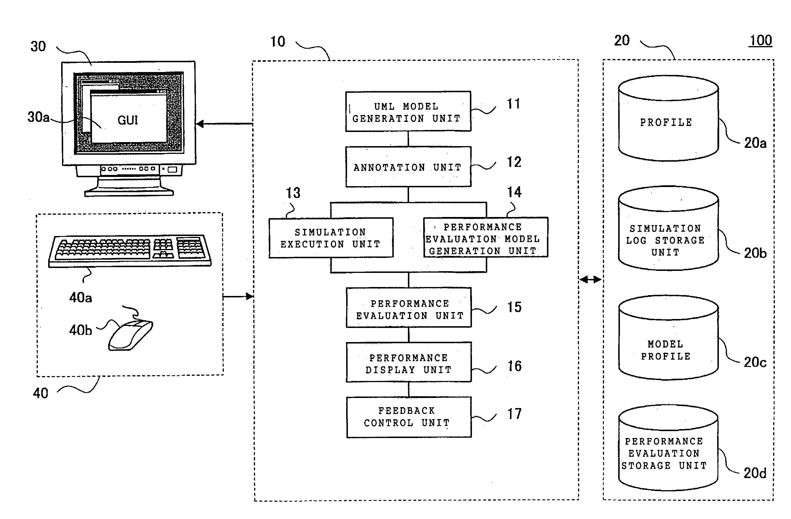
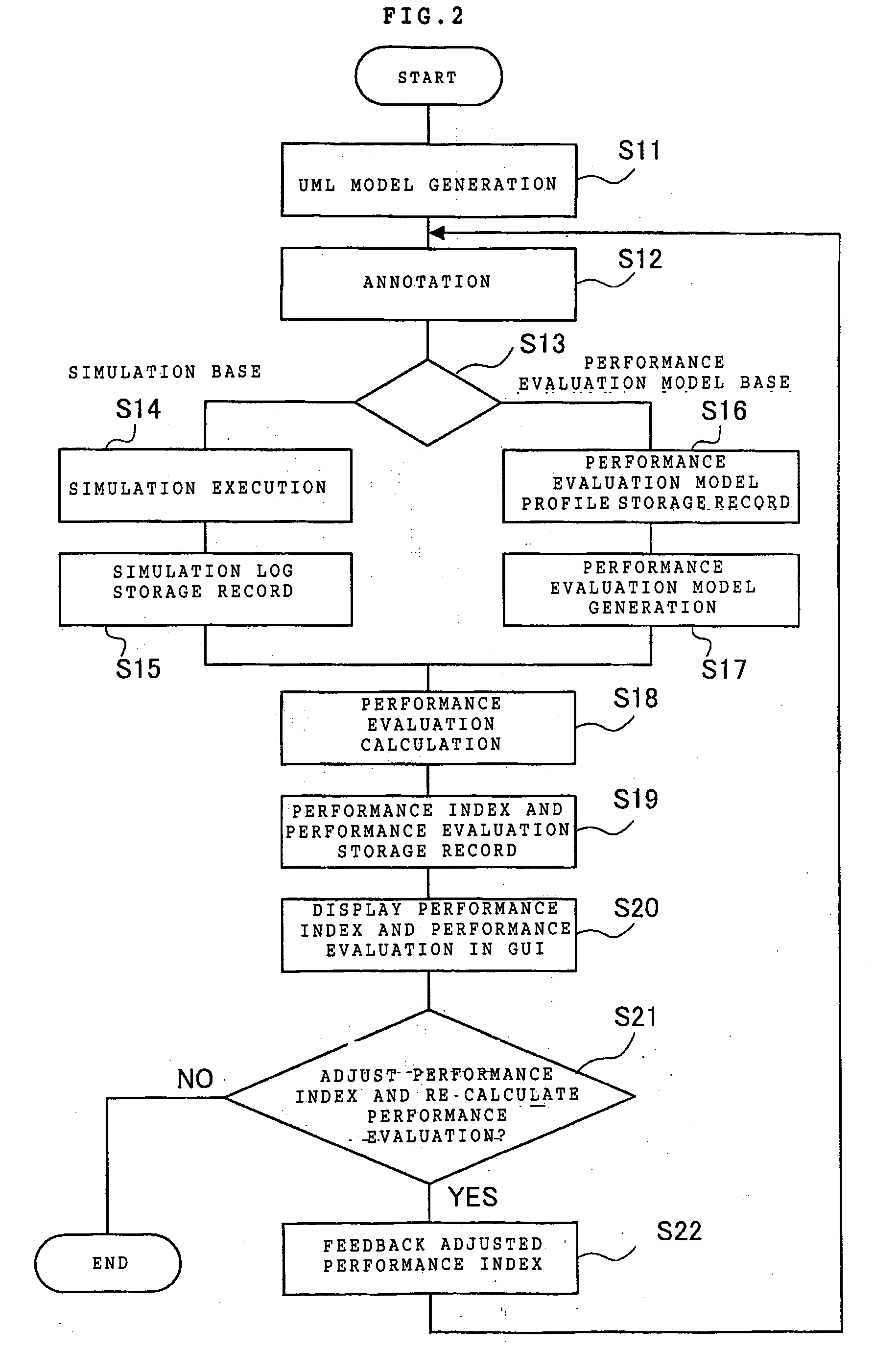
[0009] An object of the present invention is to provide a UML design method which can facilitate an architecture design pursuing optimum design parameters on the basis of viewing the whole system including both hardware and software. The UML model design method performs a design by modeling a target system based on UML, using a profile storing a design parameter. More specifically, a stereotype and a tagged value are stored in the profile as the design parameters; the stereotype and tagged value are, then, annotated to the UML model of the design target; further, the annotated stereotype and tagged value are associated to each class constituting the UML model; and the stereotype, the tagged value and the UML model, which are associated to each other, are presented on GUI (Graphical User Interface) display.
[0011] According to an aspect of the present invention concerning system design, a stereotype and a tagged value are associated with each class of a UML model, on the UML model. The classes constituting the UML model and the associated stereotypes and tagged values are displayed on the GUI. This enables architecture design, in which optimal design parameters are pursued while viewing the overall target system on the UML model. Accordingly, it is possible to increase the precision and efficiency in the system design using UML.

Problems solved by technology

However, though “XModelink” can provide a bridge to a system design taking implementation into consideration, “XModelink” does not possess a function that supports an architecture design by generating an evaluation model from a UML model.
Therefore, it is not always possible to perform an architecture design pursuing optimum design parameters on the basis of viewing the whole system including both hardware and software.

Method used


Image

  • Unified modeling language (UML) design method
  • Unified modeling language (UML) design method
  • Unified modeling language (UML) design method

Examples


Embodiment Construction

[0022] The present invention provides a UML design method which can facilitate an architecture design in pursuit of optimum design parameters on the basis of viewing a whole system including both hardware and software.

[0023] Although “XModelink” can provide a bridge to a system design taking implementation into consideration, “XModelink” does not possess a function that supports an architecture design by generating an evaluation model from a UML model.

[0024] Under the circumstances, a performance evaluation model generation device is needed. With such a device, a performance evaluation model of a design target can be automatically generated using a UML model (for instance, refer to the patent document 1, Japanese Patent Laid-Open 2001-318812). The performance evaluation model generation device consists of a UML model analysis unit, a performance evaluation model generation unit, and a performance model storage unit in which a performance evaluation model is stored. Here, the perfo...


PUM


Abstract

To provide a UML design method by which architecture design pursuing optimal design parameters while viewing the overall target system on the UML model can be performed. A UML design method of the present invention is a UML design method for performing design by modeling a target system based on Unified Modeling Language (UML), using a profile storing a design parameter, the method including the steps of: storing a stereotype and a tagged value in the profile as the design parameters; annotating a UML model of the target system with the stored stereotype and tagged value; and associating the added stereotype and tagged value with each class constituting the UML model, and displaying the stereotype and tagged value and the UML model, which are associated, on a graphical user interface.

Description

FIELD OF THE INVENTION [0001] The present invention relates to a Unified Modeling Language (UML) design method. BACKGROUND OF THE INVENTION [0002] These days, there is a strong rapidly increasing trend to satisfy the needs of a system on chip (hereinafter referred to as SoC,), on which a high performance and multi-functional processor is integrated on a single chip. In designing a SoC, it is necessary to solve a contradictory requirement that a SoC having a large and complicated configuration needs to be developed in a short period of time at low cost. [0003] Here, to meet the trend, in the system development, an architecture design needs to be conducted in an appropriate manner by performing an accurate analysis and abstraction of the system specification based on the requirements for a specification of the design target. [0004] The first version of UML was adopted as a standard of OMG (Object Management Group) in 1997. UML is a design method including an abstraction of the design ...

Claims


Application Information

Patent Timeline
IPC IPC(8): G06F17/50G06F9/44
CPCG06F17/5022G06F30/33
Inventor SAKAMOTO, MASAHARUMURAO, TAKAAKISATO, NAOTOSAITO, SHIN
Owner IBM CORP
Learn More