Device for facilitating connection of terminal ends of vehicle track to form closed loop

a technology of vehicle track and terminal end, which is applied in the direction of wire tools, manufacturing tools, transportation and packaging, etc., can solve the problems of not easily allowing for mechanical assistance or enhancement of the user's own strength, unable to meet the needs of users, and unable to achieve a high degree of control, so as to facilitate the connection and quick and efficient drawing

a technology of vehicle track and terminal end, which is applied in the direction of wire tools, manufacturing tools, transportation and packaging, etc., can solve the problems of not easily allowing for mechanical assistance or enhancement of the user's own strength, unable to meet the needs of users, and unable to achieve a high degree of control, so as to facilitate the connection and quick and efficient drawing

US20050262679A1Inactive Publication Date: 2005-12-01MARTZ DWAYNE A +3

Image

  • Device for facilitating connection of terminal ends of vehicle track to form closed loop
  • Device for facilitating connection of terminal ends of vehicle track to form closed loop
  • Device for facilitating connection of terminal ends of vehicle track to form closed loop

Examples


first embodiment

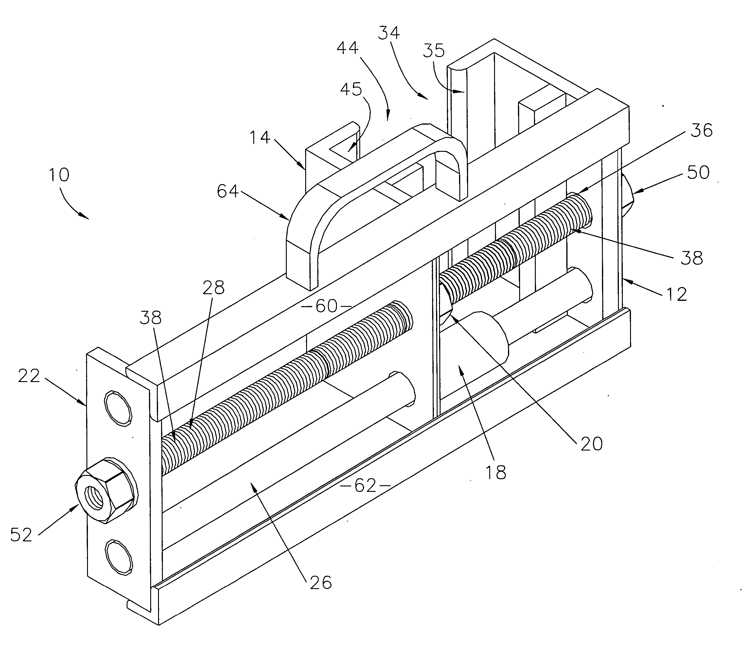
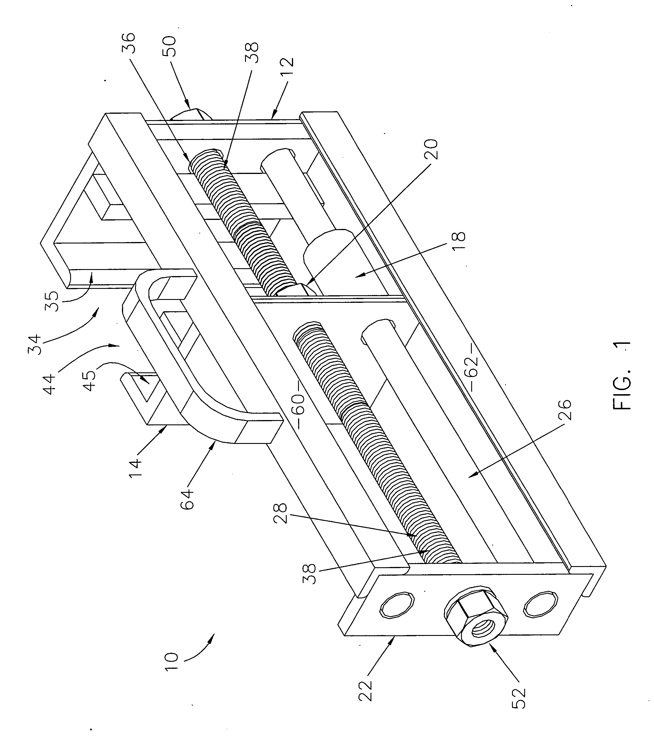
[0017]FIG. 1 is an isometric view of a preferred first embodiment of the device of the present invention using a screw-type drive mechanism;

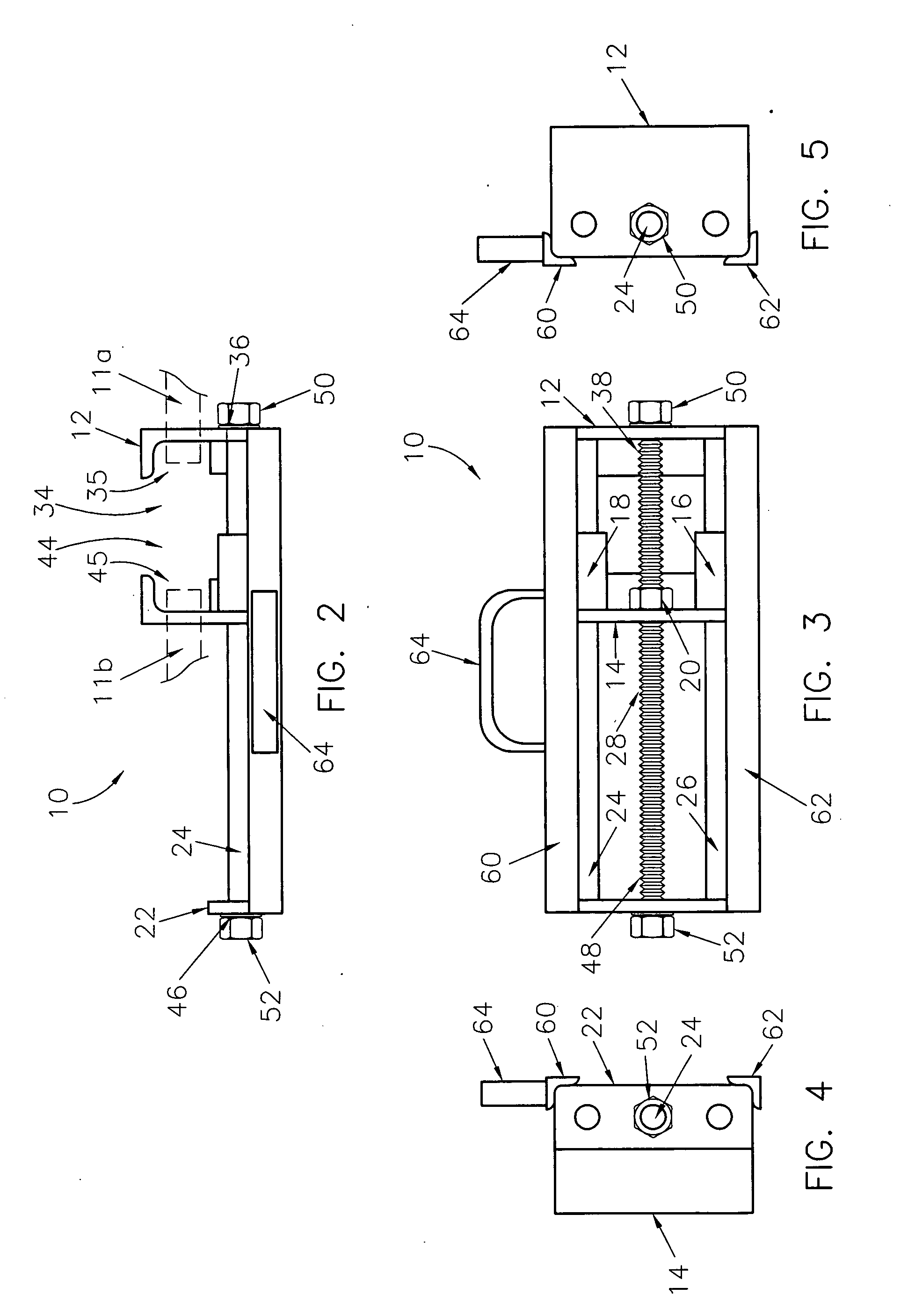
[0018]FIG. 2 is a plan view of the device of FIG. 1, with first and second terminal ends of a vehicle track shown in broken line;

[0019]FIG. 3 is a front elevation view of the device of FIG. 1;

[0020]FIG. 4 is a left side elevation view of the device of FIG. 1;

[0021]FIG. 5 is a right side elevation view of the device of FIG. 1;

second embodiment

[0022]FIG. 6 is an isometric view of a preferred second embodiment of the device of the present invention using a ratchet-type drive mechanism; and

third embodiment

[0023]FIG. 7 is an isometric view of a preferred third embodiment of the device of the present invention using a hydraulic / pneumatic-type drive mechanism.

DETAILED DESCRIPTION OF A PREFERRED EMBODIMENT

[0024] With reference to the figures, a device 10 is herein described, shown, and otherwise disclosed in accordance with preferred first, second, and third embodiments of the present invention. Generally, the device 10 facilitates engaging first and second terminal ends 11a,11b of a vehicle track and drawing the terminal ends 11a,11b together in order to facilitate their connection to form a closed or continuous loop of track.

[0025] In the preferred first embodiment, shown in FIGS. 1-5, the device 10 broadly comprises a first coupling end 12; a second coupling end 14 with parallel first and second guide sleeves 16,18 and a substantially centered internally-threaded receiver 20; a terminal guide plate 22; parallel first and second guide rods 24,26; and an externally-threaded drive rod ...


PUM


Abstract

A device for engaging first and second terminal ends of a vehicle track and drawing the terminal ends together in order to facilitate their connection to form a closed loop of track. The device comprises first and second coupling ends for engaging respective terminal ends of the track; a terminal guide plate; and two guide rods and a threaded drive rod extending between the first coupling end and the terminal guide plate and passing through the second coupling end. Fittings are provided at both ends of the drive rod. Turning either or both of the fittings causes the drive rod to turn, which causes the second coupling end to move toward the first, thereby drawing the first and second terminal ends together. In alternative embodiments, this screw-type drive mechanism is replaced by ratchet-type and hydraulic / pneumatic-type drive mechanisms.

Description

BACKGROUND OF THE INVENTION [0001] 1. Field of the Invention [0002] The present invention relates broadly to tools and other mechanisms for drawing together the terminal ends of a vehicle track so as to facilitate their connection. More particularly, the present invention concerns a device for engaging each terminal end of a vehicle track and drawing the terminal ends together in order to facilitate their connection and thereby form a closed or continuous loop of track. [0003] 2. Description of the Prior Art [0004] It will be appreciated that tracked vehicles are used in a variety of industries and endeavors, including, for example, light and heavy construction industries and military applications. Furthermore, it is known to convert certain types of wheeled vehicles to tracked vehicles in order to improve traction in, e.g., snow, mud, and similar conditions. The vehicle track typically comprises a number of track shoes flexibly connected in series by track pins, bolts, clips, or ot...

Claims


Application Information

Patent Timeline
01 Dec 2005
Publication
US20050262679A1
IPC
B23P19/04; B25B25/00; B62D55/32; H01R43/00
CPC
B25B25/00; Y10T29/53852; B62D55/32
Inventors
MARTZ, DWAYNE A.; BETLEIEWSKI, TODD A.