

Device for facilitating connection of terminal ends of vehicle track to form closed loop
- Summary
- Abstract
- Description
- Claims
- Application Information
AI Technical Summary
Benefits of technology
Problems solved by technology
Method used
Image

Examples
first embodiment
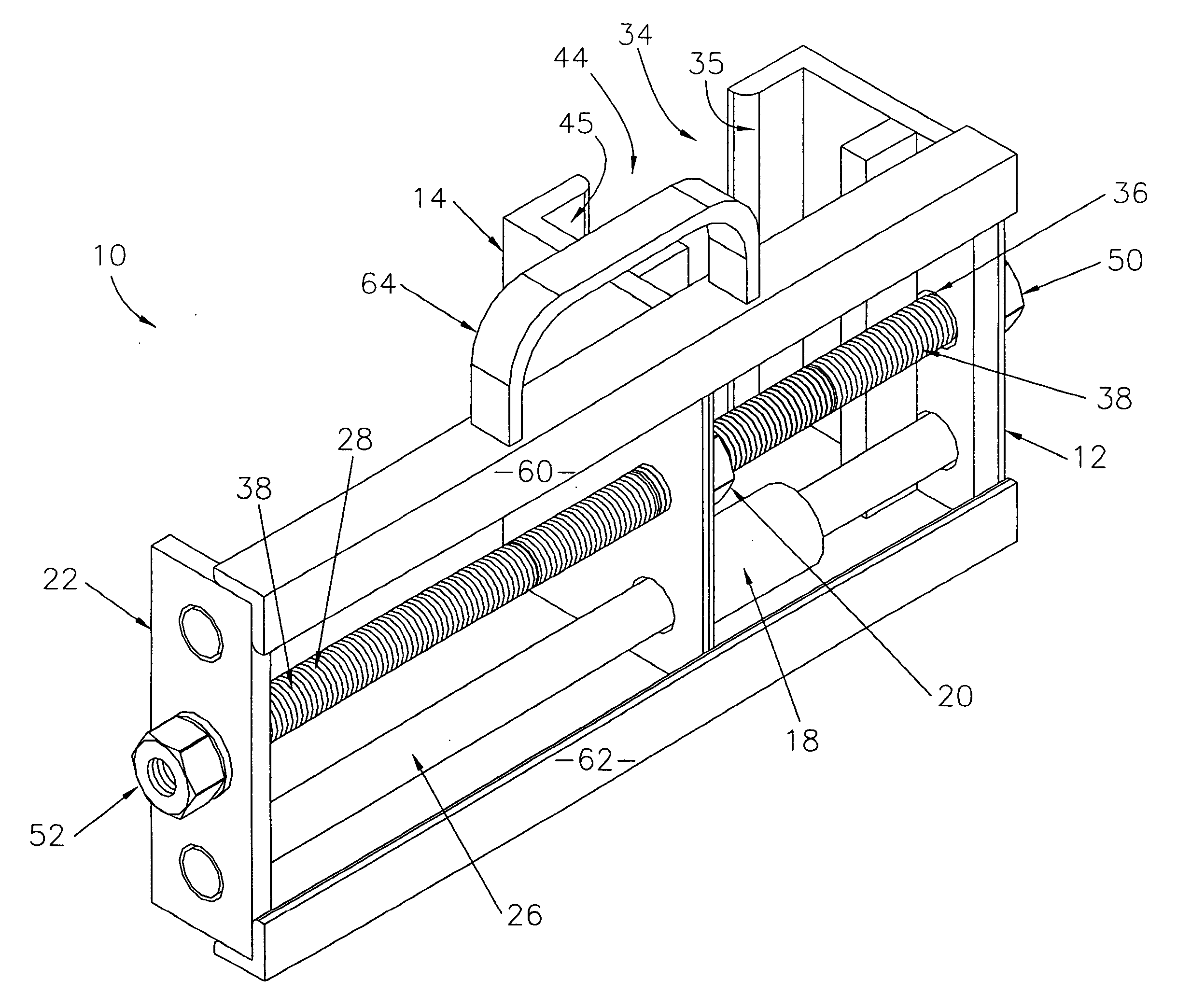
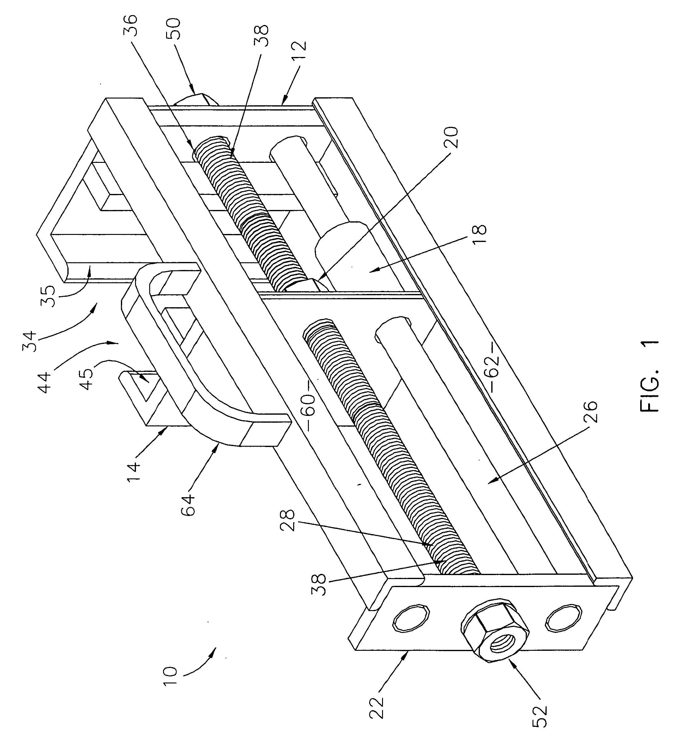
[0019]FIG. 1 is an isometric view of a preferred first embodiment of the device of the present invention using a screw-type drive mechanism;
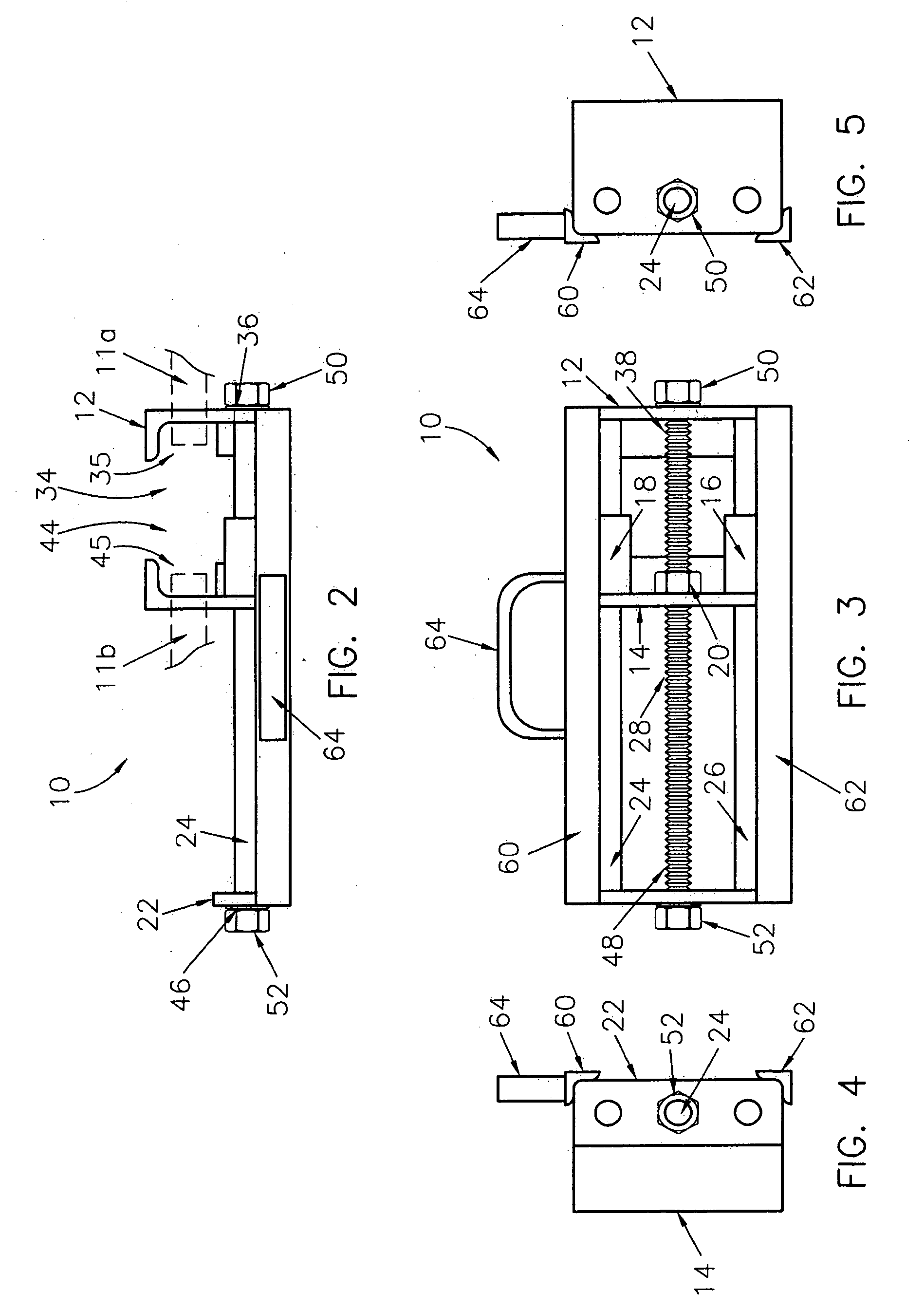
[0020]FIG. 2 is a plan view of the device of FIG. 1, with first and second terminal ends of a vehicle track shown in broken line;
[0021]FIG. 3 is a front elevation view of the device of FIG. 1;
[0022]FIG. 4 is a left side elevation view of the device of FIG. 1;
[0023]FIG. 5 is a right side elevation view of the device of FIG. 1;
second embodiment
[0024]FIG. 6 is an isometric view of a preferred second embodiment of the device of the present invention using a ratchet-type drive mechanism;
third embodiment
[0025]FIG. 7 is an isometric view of a preferred third embodiment of the device of the present invention using a hydraulic / pneumatic-type drive mechanism;
PUM
| Property | Measurement | Unit |
|---|---|---|
| Power | aaaaa | aaaaa |
| Shape | aaaaa | aaaaa |
Abstract
Description
Claims
Application Information