Orbital engine
- Summary
- Abstract
- Description
- Claims
- Application Information
AI Technical Summary
Benefits of technology
Problems solved by technology
Method used
Image
Examples
Embodiment Construction
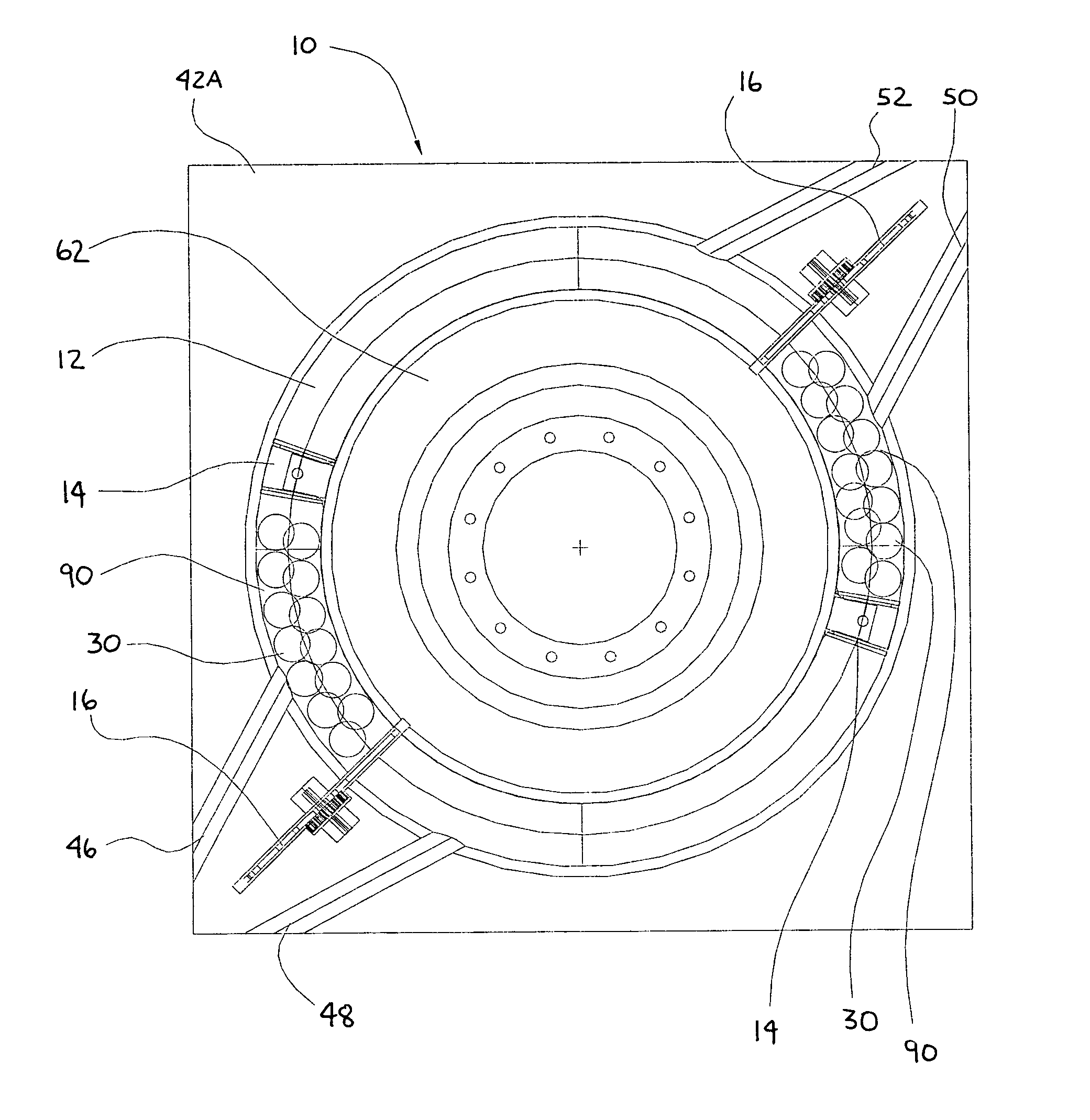
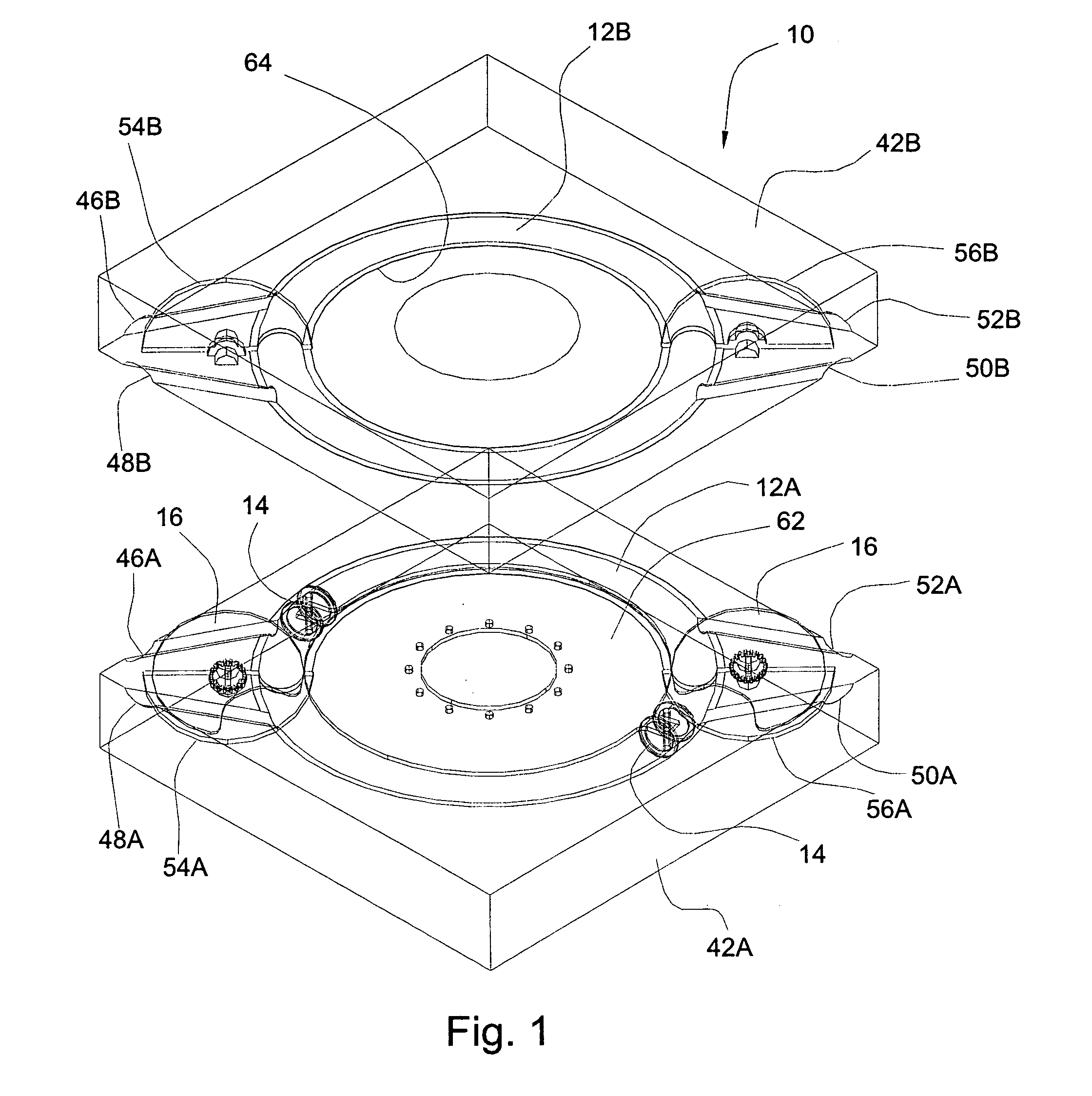
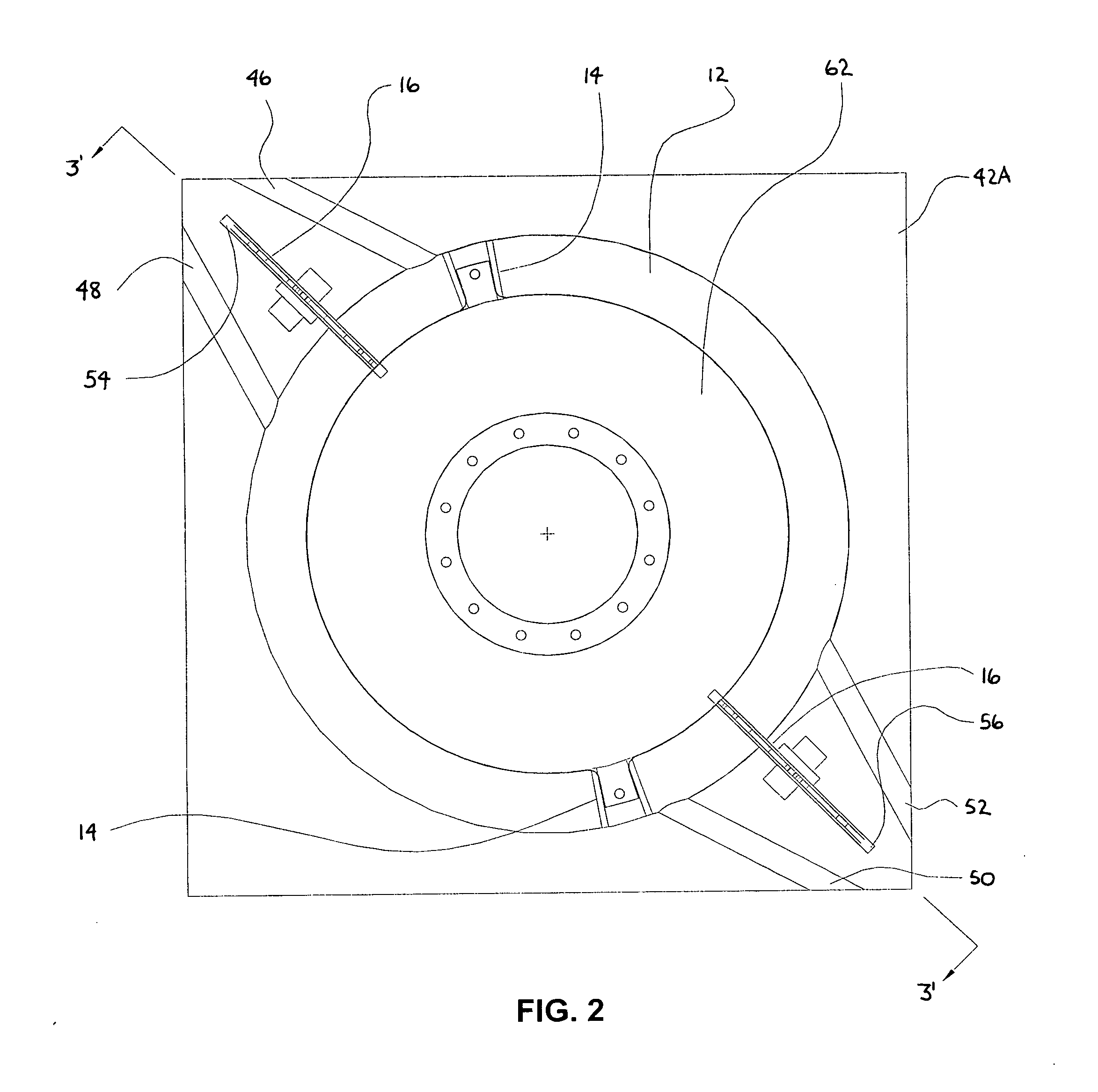
[0033] Referring now generally to FIGS. 1-15, preferred embodiments of the invention are shown. FIG. 1 is an exploded perspective view of the engine 10 of the present invention showing the two half design of the piston chamber 12. FIG. 2 is a sectional top view of a two piston 14 embodiment of the engine 10 showing the relative positioning of the various primary components of the engine 10. FIG. 3A is a sectional side view of the engine through line 3′-3′ of FIG. 2 showing the general shape of the piston chamber 12 and the positioning and operation of the chambering valves 16, which in this view are disc valves. FIG. 3B is an enlarged side view of the left side portion of FIG. 3A showing the relationship of the piston to the piston chamber and the valve cavity slot and how the connecting disc interacts with the piston chamber.
[0034]FIG. 4A is a side view of an illustrative disc valve 16 used in the engine showing a preferred single notch 80 structure. FIG. 4B is a side view of an a...
PUM
 Abstract
Description
Claims
Application Information
 - R&D
- Intellectual Property
- Life Sciences
- Materials
- Tech Scout
- Unparalleled Data Quality
- Higher Quality Content
- 60% Fewer Hallucinations
Browse by: Latest US Patents, China's latest patents, Technical Efficacy Thesaurus, Application Domain, Technology Topic, Popular Technical Reports.
© 2025 PatSnap. All rights reserved.Legal|Privacy policy|Modern Slavery Act Transparency Statement|Sitemap|About US| Contact US: help@patsnap.com


