Pressure monitoring of control lines for tool position feedback

a technology of pressure monitoring and control lines, applied in the direction of survey, borehole/well accessories, construction, etc., can solve the problems of inaccurate fluid volume measurement techniques, inability to measure fluid volume, and inability to accurately determine position

Active Publication Date: 2005-12-01
BAKER HUGHES INC
View PDF12 Cites 65 Cited by
  • Summary
  • Abstract
  • Description
  • Claims
  • Application Information

AI Technical Summary

Benefits of technology

[0009] In one aspect of the present invention, a flow control device for use in a wellbore to allow flow of formation fluid into the wellbore comprises a valve member adapted to move when disposed in the wellbore. A fluid line supplies a working fluid under pressure to move the valve member to allow the fluid to flow into the wellbore. A sensor in the wellbore, and associated with the fluid line, provides an indication of a position of the valve member.
[0010] In another aspect, a downhole flow control device comprises a hydraulically-actuated sleeve valve that is operable between a first position wherein the valve is in a first fluid flow state and a second position wherein the valve is in a second fluid flow state. A hydraulic control line is operably associated with the sleeve valve for supplying hydraulic fluid to operate the valve between states. A downho

Problems solved by technology

In some instances, however, such as with a subsea pod, it may not be possible to measure fluid volume.
Also, the fluid volume measurement technique may be inaccurate at times for a variety of reasons, including leaks within the hydraulic control lines and connections or at seals that lead to fluid loss, which leads to an incorrect determination of position.
In ad

Method used


Image

  • Pressure monitoring of control lines for tool position feedback
  • Pressure monitoring of control lines for tool position feedback
  • Pressure monitoring of control lines for tool position feedback

Examples


Embodiment Construction

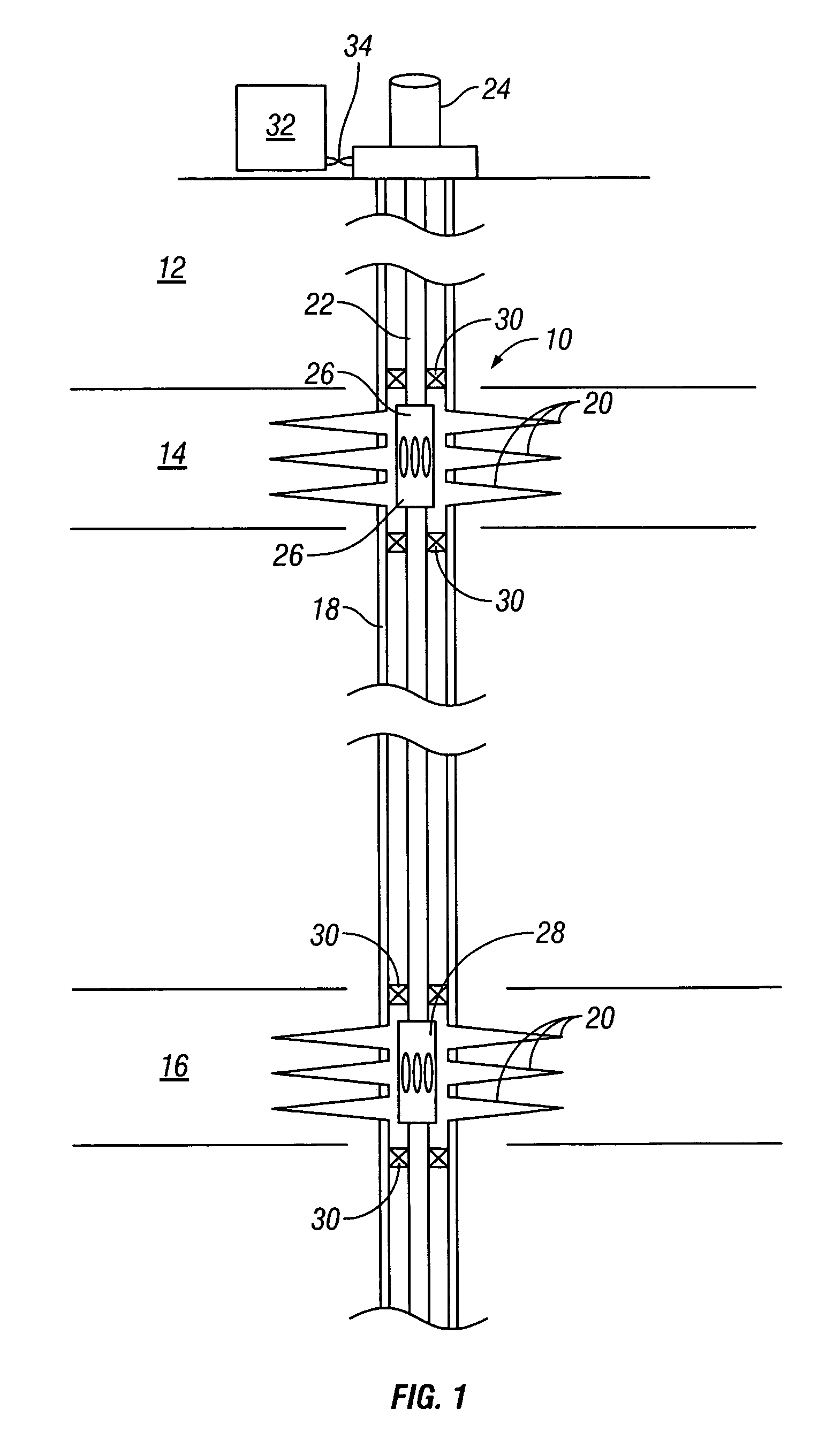
[0020]FIG. 1 illustrates an exemplary production well 10 that penetrates the earth 12 into multiple hydrocarbon zones, such as zones 14, 16. The well 10 is cased with casing 18, and perforations 20 are disposed through the casing 18 proximate each of the zones 14, 16 to provide a flow point for hydrocarbon fluids within the zones 14, 16 to enter the well 10. It is noted that, although a single wellbore is shown, there may, in practice, be a plurality of multilateral wellbores, each penetrating one or more zones such as zones 14, 16. Additionally, although only two zones are shown, those skilled in the art will recognize that there may be more such zones.

[0021] A production tubing string 22 is disposed within the well 10 from a wellhead 24 and includes flow control devices 26, 28 located proximate the zones 14, 16, respectively. Packers 30 isolate the flow control devices 26, 28 within the well 10. In one embodiment, each of the flow control devices 26, 28 is a sliding sleeve flow c...


PUM


Abstract

A flow control device for use in a wellbore to allow flow of formation fluid into the wellbore comprises a valve member adapted to move when disposed in the wellbore. A fluid line supplies a working fluid under pressure to move the valve member to allow the fluid to flow into the wellbore. A sensor in the wellbore, and associated with the fluid line, provides an indication of a position of the valve member. A method of determining a state of a flow control tool within a wellbore comprises supplying fluid under pressure to the flow control tool to move a flow control member of the tool into the state. Pressure of the supplied fluid is detected downhole. The state of the flow control device is determined from the detected pressure of the supplied fluid.

Description

CROSS-REFERENCE TO RELATED APPLICATIONS [0001] This application claims the benefit of U.S. Provisional Application No. 60 / 576,202, filed Jun. 1, 2004, which is incorporated herein by reference.BACKGROUND OF THE INVENTION [0002] 1. Field of the Invention [0003] The invention relates generally to the hydraulic control of downhole tools and, particularly to methods and devices for determining the state of such hydraulically-actuated tools. [0004] 2. Description of the Related Art [0005] Production of hydrocarbons from a downhole well requires subsurface production equipment to control the flow of hydrocarbon fluid into the production tubing. Typical flow control equipment might include a sliding sleeve valve assembly or other valve assembly wherein a sleeve is moved between open and closed positions in order to selectively admit production fluid into the production tubing. The valve assembly is controlled from the surface using hydraulic control lines or other methods. [0006] In a simp...

Claims


Application Information

Patent Timeline
IPC IPC(8): E21B47/12E21B23/00E21B33/12E21B34/16E21B43/12E21B47/09E21B47/10
CPCE21B23/006E21B34/10E21B2034/007E21B43/12E21B34/16E21B2200/06E21B23/004
Inventor VACHON, GUY
Owner BAKER HUGHES INC
Why Eureka
Try Eureka